6 Functional Description of the Ethernet Modules
6-18
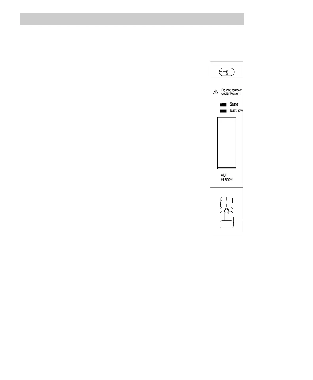
Description of the status indicators
The module EI 802F has a multicolor LED which indicates the current module state:
State LED
Off No voltage applied, module is isolated
Green Power supply switched on, module identified and
ready to operate according to configuration.
Orange Power supply switched on, module identified:
- intermediate state after normal module startup or
- configuration mode of Boot Loader (see Section
5.4)
Orange flashing Power supply switched on, module identified;
module not connected to a proper bus structure.
Red Power supply switched on:
- module not yet identified (short time, during
module startup) or
- error occurred during module test
Batt low LED
Off Sufficient buffer battery voltage.
Yellow Buffer battery not found or low (insufficient
voltage).
6.4.2 Hardware structure
The AUI module EI 802F comprises the following hardware components:
• LAN controller/coprocessor, adapted to Intel RISC-CPU
32-bit data bus, 32-bit address bus, DMA, interrupt
• Serial interface/Manchester encoder for generating a serial bit stream
• EEPROM for configuration data.
• Regulated 12V power supply for AUI interface
• Isolator for electrical isolation of the bus signals
• Buffer battery holder with polarity reversal protection and monitoring circuit
• 15-pin SUB-D socket with slide lock for AUI interface