4 Cabling the AC 800F
4-96
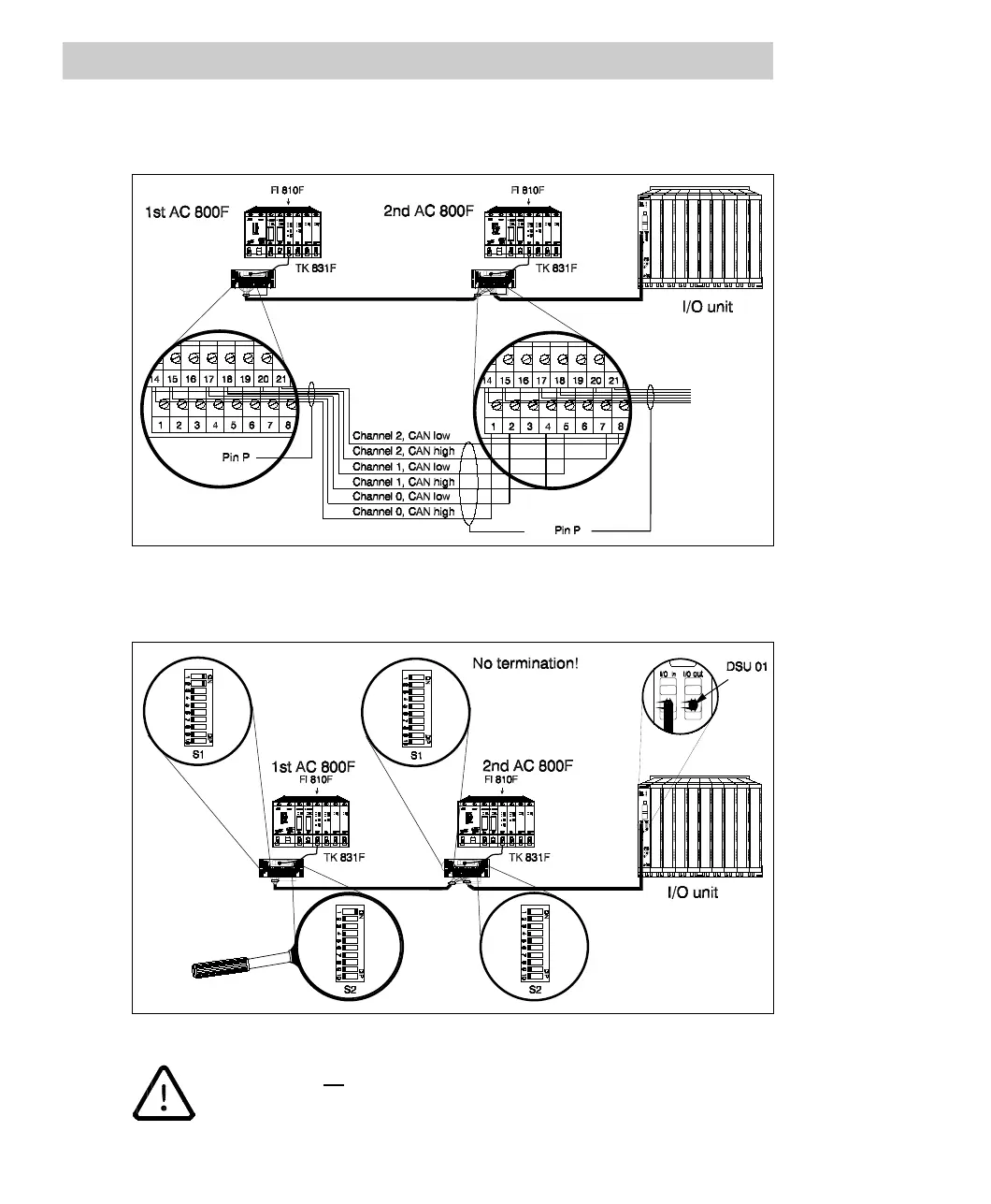
Fig. 4-75 shows the redundant cabling of two AC 800F with one CAN module FI 810F
at each end of the bus cable.
Fig. 4-75 Redundant connection of the CAN bus, case 1
Terminate the individual components as seen in the illustration.
Fig. 4-76 External termination for redundant connection
Make sure that no jumpers are set on the modules FI 810F and that the
switches on the internal terminal block TB 870F areintheOFF position.