5 AC 800F Functional Description
5-22
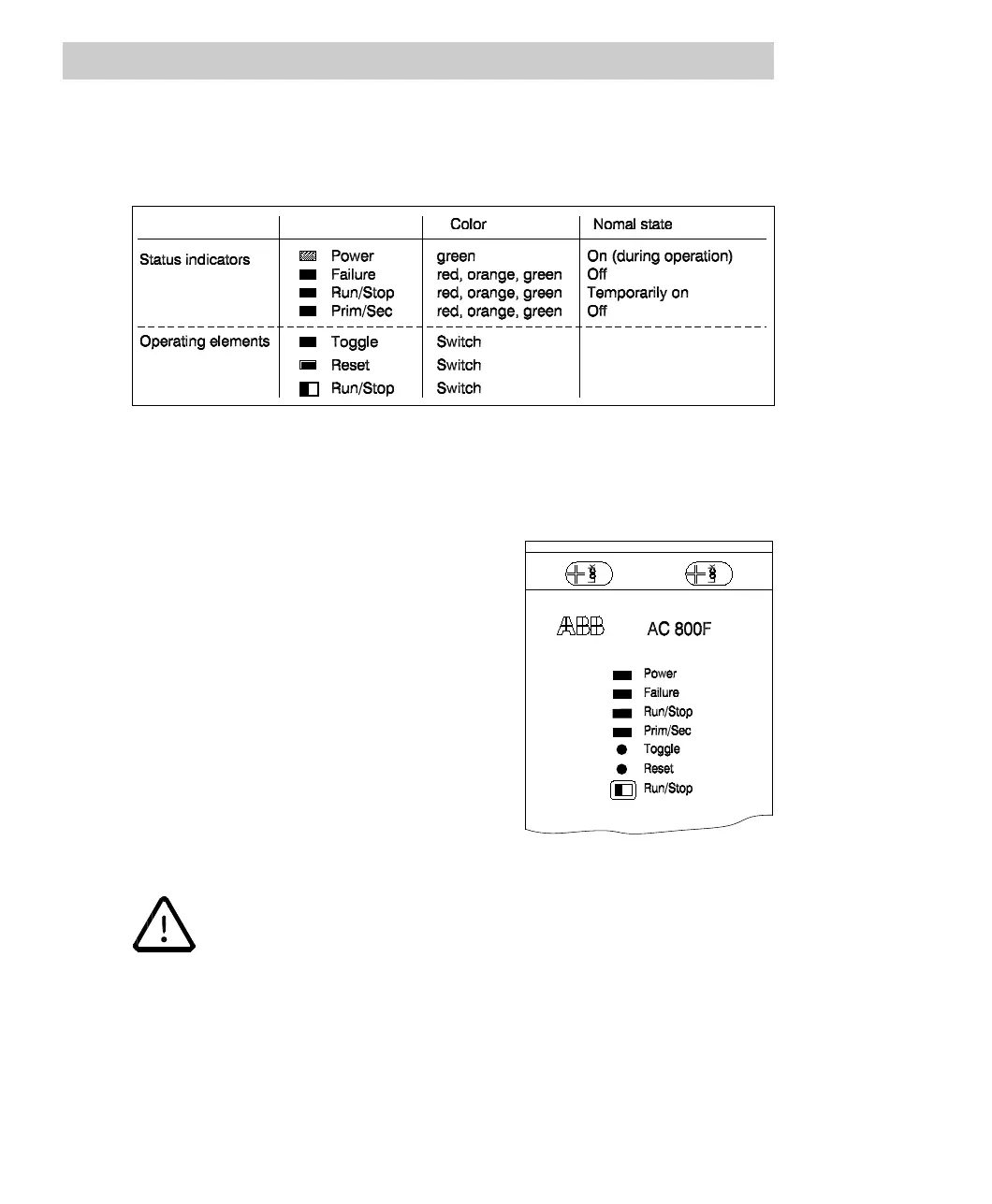
5.3.3 Status indicators of the power supply module
Figure 5-14 shows the status indicator LEDs and operating elements on the AC 800F
power supply module.
Fig. 5-14 Status indicators and operating elements on power supply module
The LEDs indicate the following:
Power
Indicates that all supply voltages for the AC 800F
are applied.
Failure
Indicates internal error states of the AC 800F. If
the Failure LED lights up red, connect a
diagnostic terminal or diagnostic PC. Refer to
Section 5.4 for further instructions.
• If the coding switch on the Ethernet module has been set to position 0,
enter a valid IP address via the diagnostic interface. Prior to setting the
new IP address set the Run/Stop switch on the power supply module
to Stop. Otherwise, the Failure LED starts flashing.
• While the self-test is being run or after a cold or warm restart, the LED
lights up orange. If an error is detected during the self-test, the LED is
permanently lighted red. Otherwise, the LED will be extinguished after
termination of the self-test.