5 AC 800F Functional Description
5-2
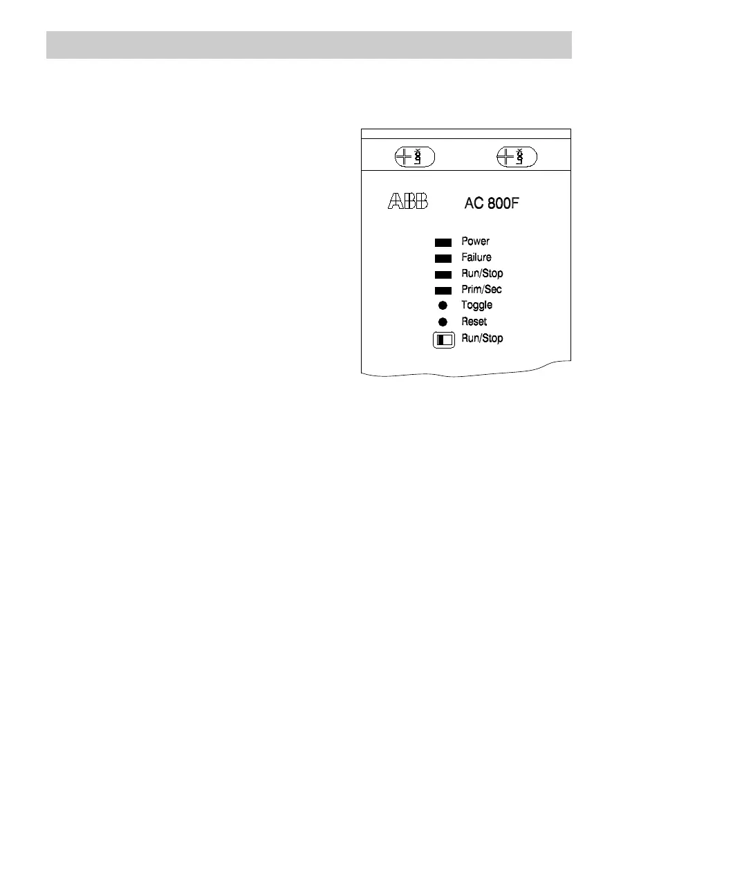
All indicators and operating elements of the AC 800F CPU are located on the front
panel of the power supply module.
The operating system controls the colors of
the Failure, Run/Stop and Prim/Sec LEDs.
Refer to Section 5.3 for details.
The Reset switch is recessed to avoid
unwanted actuation by accident. It can only
be pressed by using a "tool" like a ball pen or
similar. No tool is required for actuating the
Toggle switch and the Run/Stop switch. The
Toggle switch is used to toggle between the
Primary and the Secondary in redundancy
mode.
The appropriate power supply and the 9-pin
Sub-D connector for the diagnostic interface
(see Sections 4.1.5 and 5.4) are located in
the lower part of the front panel.
5.1.1 Power supply module SA 801F, input voltage 115 - 230 V AC
Features
- Wide range input 115 - 230 V AC with EMC filter
- Functional extra low voltage with protective separation on the output
- 3.3 V DC, ± 3 %, 5 A and 5.0 V DC, ± 3%,5A;
Output voltages with step down switch controllers. Total output power 26.5 W
- Input and output voltage monitoring. Power-fail signal
- Overcurrent delimiter, permanently short-circuit proof
- More than 20ms bridging in case of power failure
- Diagnostic interface (with EMC filter)
- EEPROM for manufacturing and diagnostic data
- Status indicators and operating elements for AC 800F CPU board