4 Cabling the AC 800F
4-60
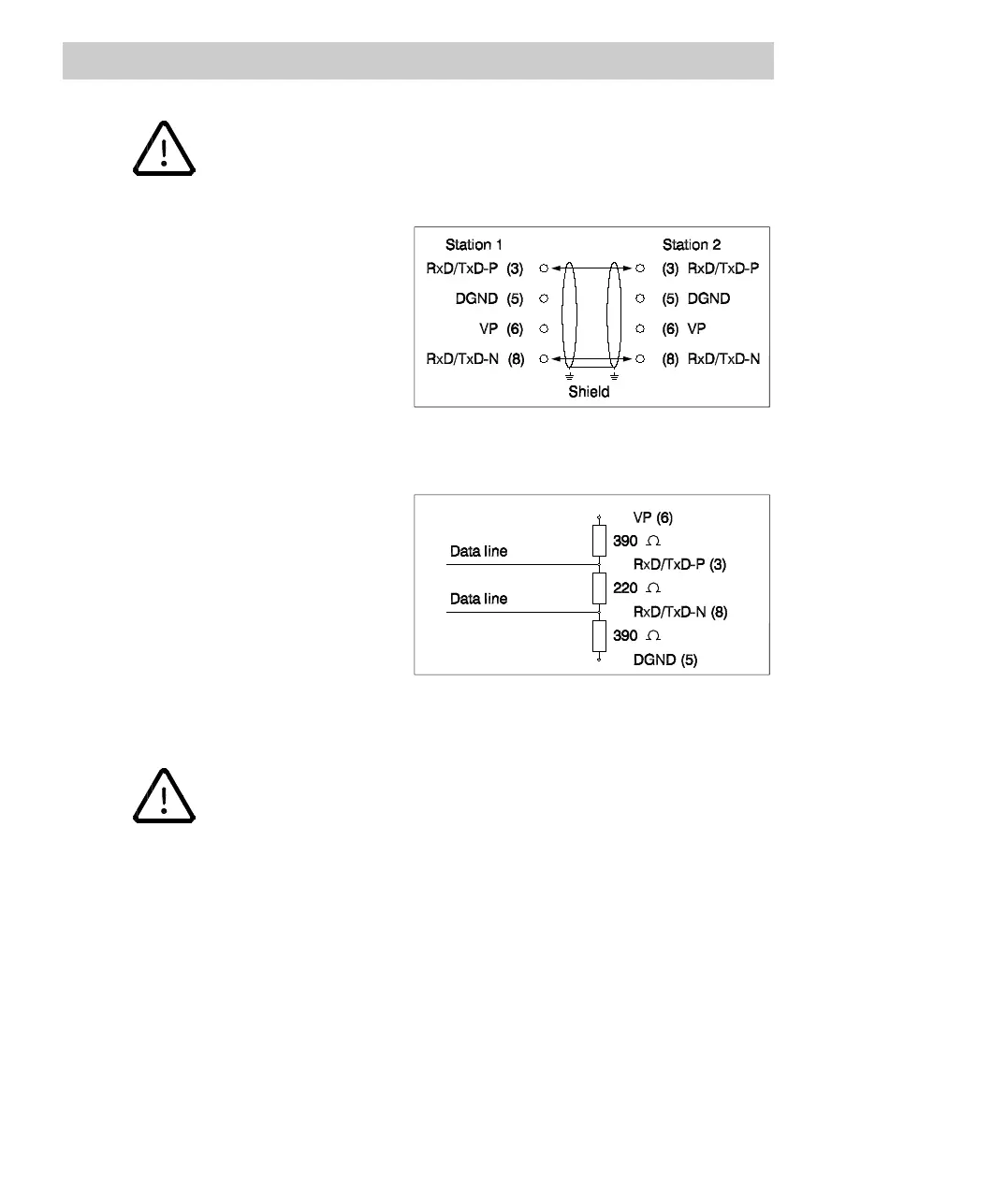
When connecting the nodes make sure that the data lines are not
distorted or confounded.
The RxD/TxD-P signal wire
connected to pin 3 of the Profibus
module connector must be
connected to the relevant signal
wires with the same designation
of all nodes.
Proceed accordingly with the
RxD/TxD-N signal lines on pin 8
of the connector.
Fig. 4-36 Cabling FI 830F
The bus is terminated at each
end of a segment with a bus
termination.
If the Profibus module is located
at the end of a line, make sure
that a bus termination, which may
be connected into the line, is
available in the Profibus
connector.
Fig. 4-37 FI 830F bus termination
To ensure trouble-free operation, make sure that the two bus
terminations are always under power.
If the installation contains areas with high potential differences, a potential
equalization cable should be added to the data line when using an RS485 Profibus
cable. The potential equalization cable must have a minimum cross-sectional area of
16 mm
2
and must be linked with the shield of each node. This avoids compensation
currents through the cable shield or data lines. A more flexible solution is provided by
fiber-optic cables.