4 Cabling the AC 800F
4-70
4.3.2 Cabling the serial fieldbus module FI 820F
The serial fieldbus module FI 820F has two serial communication
channels. The channels can be used as RS232, RS422 or RS485
interfaces, as required. The signals from each of the three interface
types are applied to different pins of the 26-pin connector.
Therefore, no jumpers setting is required to configure the module.
Setting up the interface in the ControlBuilder F configuration mask
will do.
Both of the channels are electrically isolated from each other and
from the system and can be used with either of the three interface
types. The FI 820F module is provided with a bus termination
which can be activated by setting the respective jumpers. The
termination consists of three terminating resistors (1 kohm pull-up,
100 ohms differential, 1 kohm pull-down). The module voltage is
used as the terminating voltage, i.e. the entire bus is unterminated
when the module is switched off. If you should not want to
terminate your bus in this way, it is recommended to use an
external termination on the terminal block TB 870F with external
supply.
Use cable TK 821F to connect module FI 820F to a terminal block
TB 870F. A termination of RS422 and RS485 can also be provided
on the terminal block TB 870F. The terminal block TB 870F is also
used for making the necessary field cabling. The interface type is
selected by using the appropriate cable which only feeds the
required signals to the terminal block TB 870F.
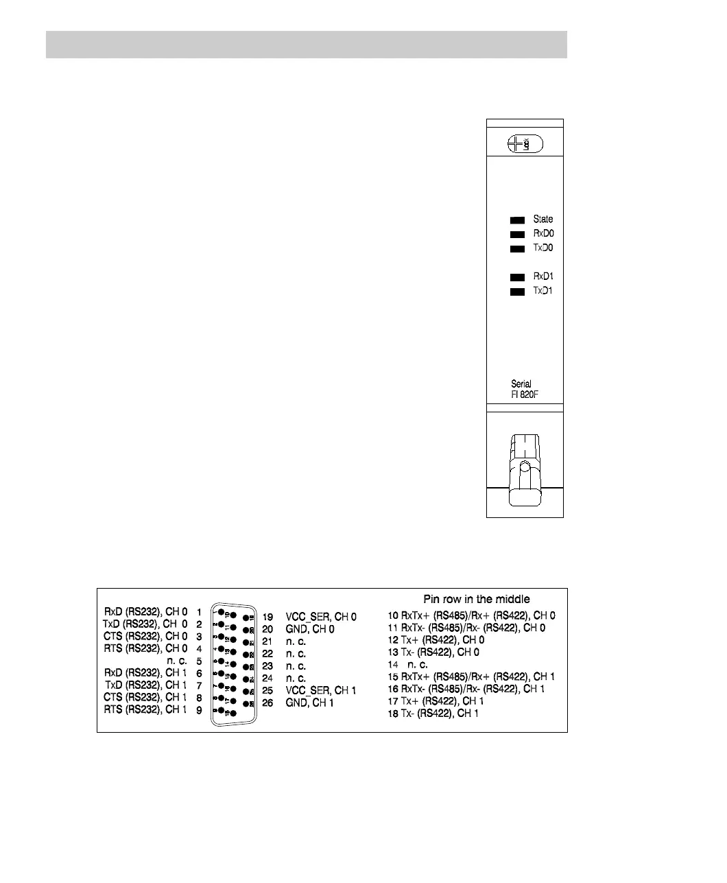
FI 820F connector pin assignment
Fig. 4-46 FI 820F connector pin assignment
Channel 0 corresponds to Ser 1, channel 1 corresponds to Ser 2.