7 Functional Description of the Fieldbus Modules
7-23
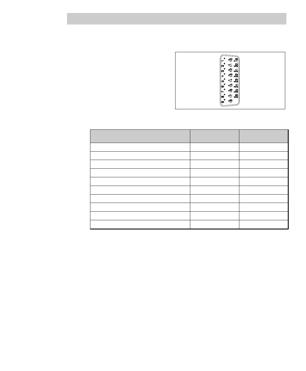
Connector pin assignment
Pin assignment of the communi-
cation connector (26-pin HD-Sub-D
socket, shape factor 15-pin)
Fig. 7-11 FI 820F connector pin assignment
Signal Channel 0 Channel 1
RxD (RS232) Pin 1 Pin 6
TxD (RS232) Pin 2 Pin 7
CTS (RS232) Pin 3 Pin 8
RTS (RS232) Pin 4 Pin 9
GND Pin 20 Pin 26
VCC_Term Pin 19 Pin 25
RxTx+ (RS485)/Rx+ (RS422) Pin 10 Pin 15
RxTx- (RS485)/Rx- (RS422) Pin 11 Pin 16
Tx+ (RS422) Pin 12 Pin 17
Tx- (RS422) Pin 13 Pin 18
Electrical isolation
The two serial channels are electrically isolated from each other and from the system.
To achieve this, the communication signals are isolated through high-speed
optocouplers. The power for the channels is provided by an electrically isolated
DC/DC converter with two isolated output voltages.