5 AC 800F Functional Description
5-8
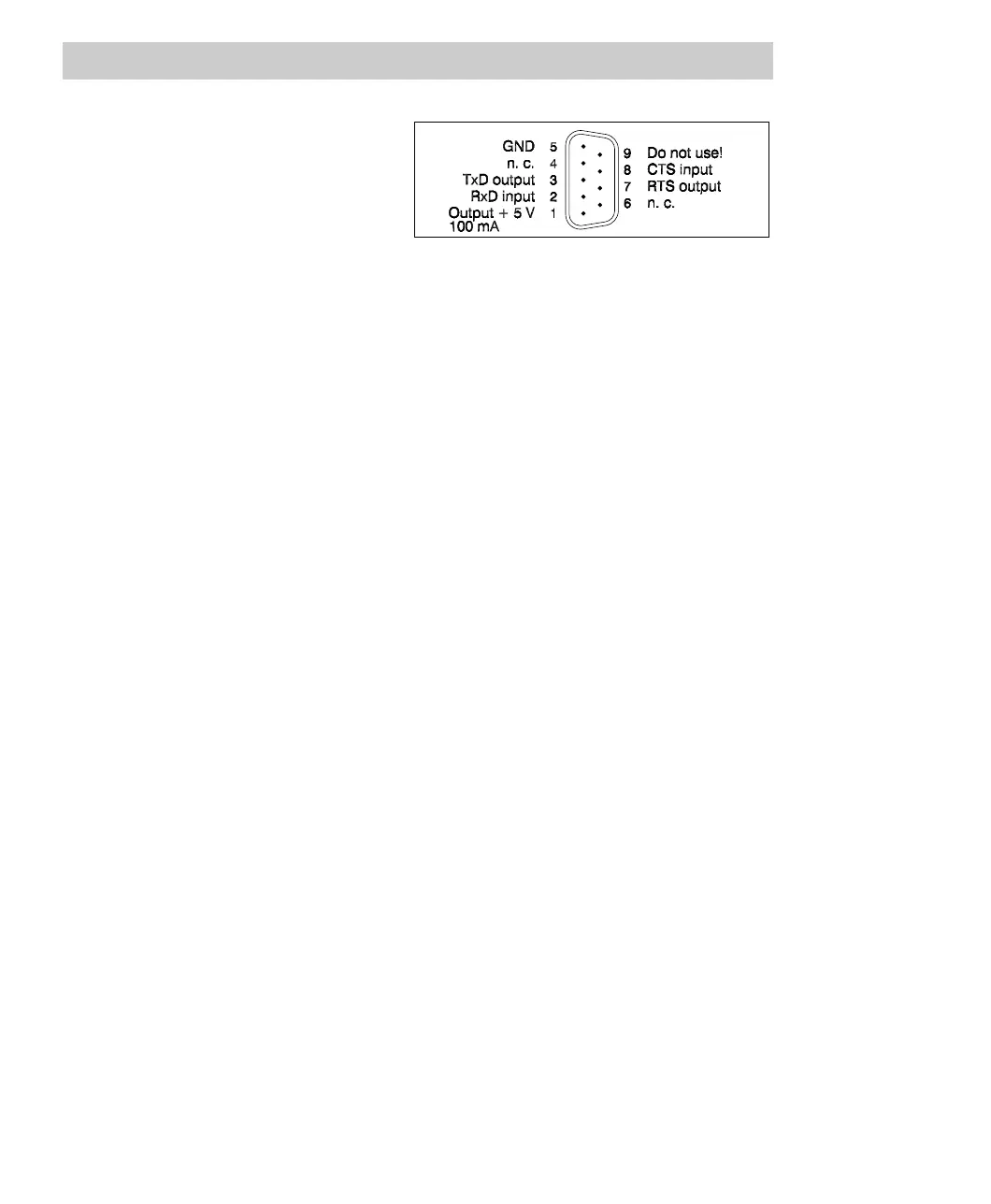
Diagnostic connector
Use one of the ready-made
TK 890F or TK 891F cables for
connecting a diagnostic interface,
see Section 4.1.5 and Section 5.4.
Fig. 5-9 Pin assignment of diagnostic connector
Technical data of SD 802F
Input voltage 24 V DC. Perm. range 19.2 ... 32.5 V DC.
Perm. ripple 14 % peak-peak, supply via
three-phase bridge rectifiers permissible.
Mains frequency DC input, therefore not applicable
Protection against polarity reversal yes
Protection against improper voltage
values and/or frequency
application of voltages below nominal
voltage does not cause destruction,
Bridging time in case of power failure > 20 ms without malfunctions
Fuse subminiature fuse type 3.15 AT, in input
circuit, for each supply
Output voltages
3.3 V DC (± 3%),
5.0 V DC (± 3%)
Output current 0.5 ... 5 A to 3.3V and 5.0V
Total output power max. 26.5 W
Current limiting above approximately 6 A, automatic restart
of normal operation
Input current at nominal load 1.3 A at 24 V DC
Rated input power 31 W
Inrush current max. 15. times the peak value of the nominal
current (NAMUR)
Efficiency around 86 %
Thermal power loss with nominal load 5 W
Weight 460 g
Connectors Power connector
Diagnostic interface
Module/CPU board
2-pin housing connector GSSA200,
from Hirschmann
9-pin Sub-D connector (male)
96-pin connector