7 Functional Description of the Fieldbus Modules
7-33
7.5.2 Hardware structure
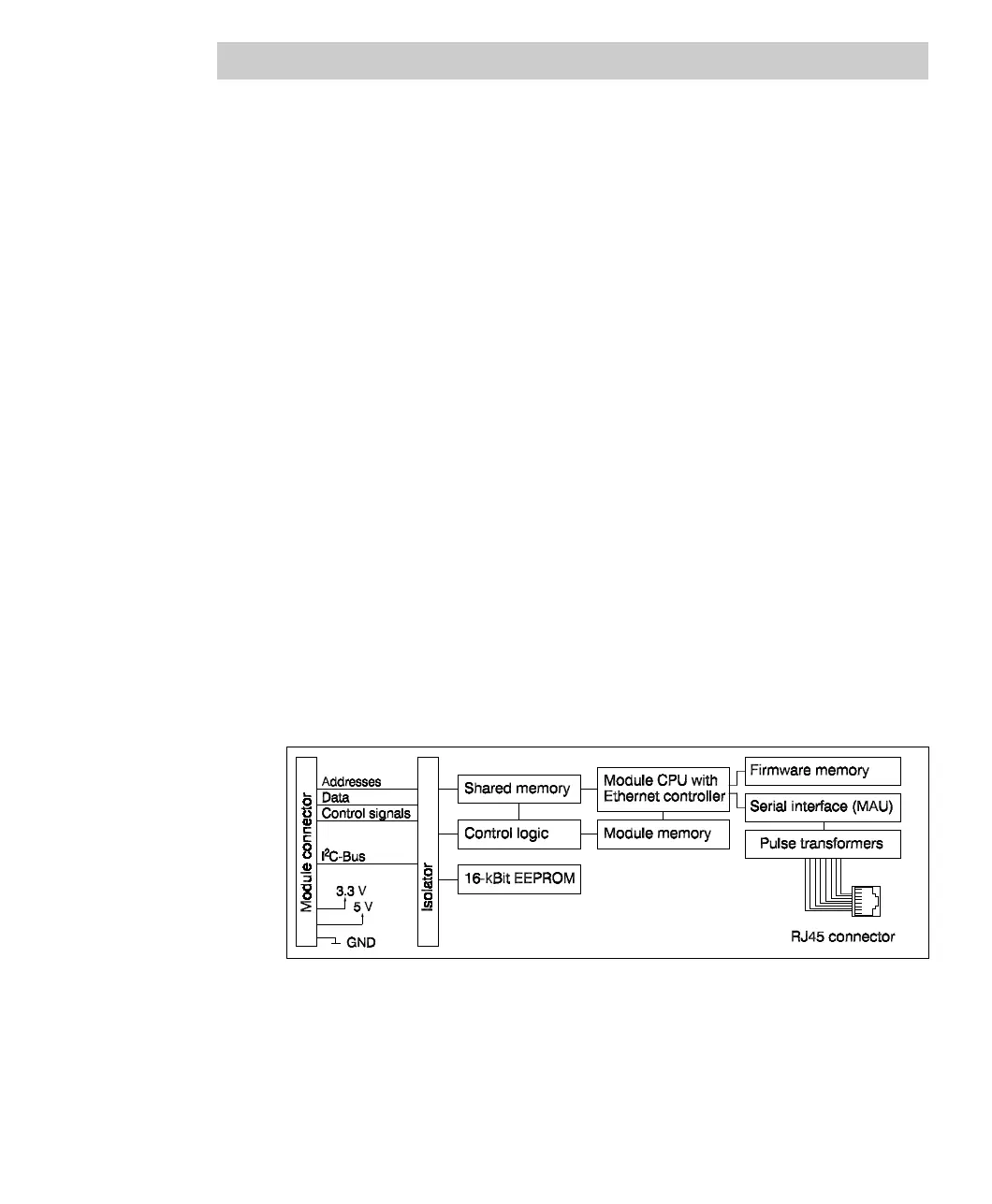
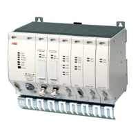
The FF/HSE module FI 840F comprises the following hardware components:
• ARM-CPU with integrated Ethernet controller, 32-bit data bus, 32-bit address bus
• Internal flash EPROM for the module CPU and protocol software; software and
firmware updates possible without exchanging the EPROM.
• Internal main memory as RAM for the module CPU
• Shared memory for data exchange between main processor and module CPU;
data storage through parity check
• Automatic recognition whether 10BaseT or 100BaseTX is connected
• Electrically isolated TP interface
• ESD protector on RJ45 socket
• Serial interface/Manchester encoder for generating a serial bit stream
• EEPROM for configuration data and diagnostic data buffer, independent of the
buffer battery
• Isolator for electrical isolation of the bus signals
• RJ45 socket with two Link LEDs
Block diagram
Fig. 7-14 FF/HSE module block diagram


 To Next Page