5 AC 800F Functional Description
5-10
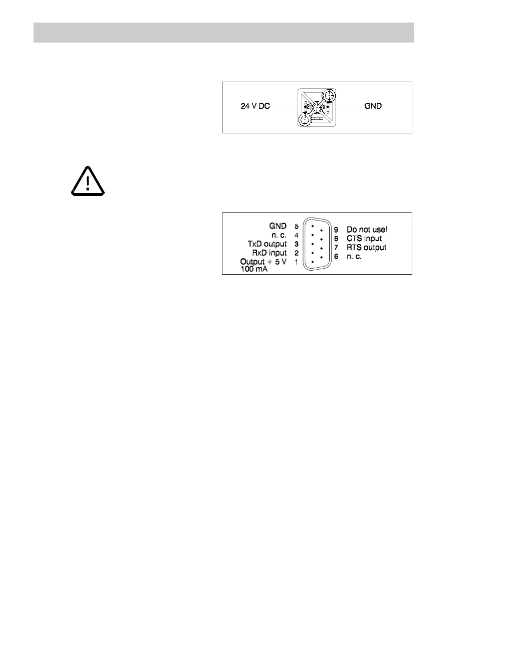
Connector pin assignment
DC mains connector
Use the ready-made TK 802F
power cable for connecting a
24 V DC supply voltage, see
Section 4.1.5.
Fig. 5-11 Pin assignment of DC mains connector
Note that power supply module SD 812F must be supplied with extra
low voltage with protective separation from other circuits.
Diagnostic connector
Use one of the ready-made
TK 890F or TK 891F cables for
connecting a diagnostic interface,
see Section 4.1.5 and Section 5.4.
Fig. 5-12 Pin assignment of diagnostic connector
Technical data of SD 812F (preliminary)
Input voltage 24 V DC. Perm. range 19.2 ... 32.5 V DC.
Perm. ripple 14 % peak-peak, supply via
three-phase bridge rectifiers permissible.
Mains frequency DC input, therefore not applicable
Protection against polarity reversal yes
Protection against improper voltage
values and/or frequency
application of voltages below nominal
voltage does not cause destruction,
Bridging time in case of power failure > 20 ms without malfunctions
Fuse subminiature fuse type 3.15 AT, in input
circuit, for each supply
Output voltages
3.3 V DC (± 3%),
5.0 V DC (± 3%)
Output current 0.5 ... 6.5 A to 3.3 V and
0.5 ... 5.5 A to 5.0 V
Total output power max. 35 W
Current limiting above approximately 7.5 A, automatic restart
of normal operation
Input current at nominal load 1.7 A at 24 V DC