6 Functional Description of the Ethernet Modules
6-26
Pin: Signal Description
1 GND Collision signal, shield
2 COL(+). Collision signal +
3 TRM(+) Transmit signal +
4 GND Receive signal, shield
5 RCV(+) Receive signal +
6 GND Transceiver supply, ground
7 n. c. Not used
8GND
9 COL(-). Collision signal -
10 TRM(-) Transmit signal -
11 GND Transmit signal, shield
12 RCV(-) Receive signal -
13 +12 V Transceiver supply +
14 GND Transceiver supply, shield
15 n.c. Not used
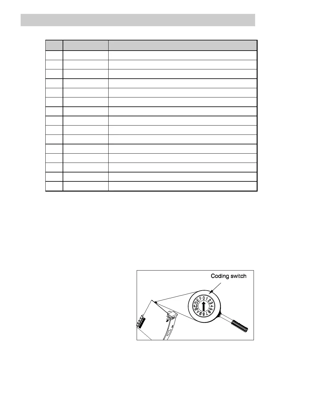
6.5.3 Operating elements
Coding switch for adjusting the IP address
The possibility to adjust the IP address on every node is the prerequisite for connect-
ing the node to an IP network. The AC 800F IP address is assigned or configured by
the operating system, but it is defined by setting the coding switch on the Ethernet
module.
The coding switch is located at
the top edge of the Ethernet
module. Use a screw driver with a
blade width of 2 ... 2.5 mm for
setting the coding switch.
The switch can snap in positions
0 ... 9 and A ... F. It can be turned
both clockwise and counter-
clockwise.
Fig. 6-14 AUI module coding switch
Refer to Sections 5.3.1 and 5.4.4 for details.