7 Functional Description of the Fieldbus Modules
7-22
7.3.2 Hardware structure
The following hardware components are used in the serial module:
• Serial controller (UART, two-channel)
• RS232 driver for RxD, TxD, CTS, RTS for each channel
• RS422 driver for RD+, RD-, TD+, TD- for each channel
• RS485 driver for RxTx+, RxTx- for each channel
• Three 16-bit hardware counters as protocol time base.
• High-speed optocouplers for electrical isolation of the communication signals
• Discrete DC/DC converter with two electrically isolated output voltages for the
communication channels
• Optocouplers for monitoring the electrically isolated voltages and, thus, possibility
of alarm signaling in case of failure
• EEPROM for configuration data and error memory
• Isolator allowing you to plug the module in or remove it while the AC 800F is
running.
• 26-pin high-density Sub-D socket with the signals of the two channels
In order to ensure electromagnetic compatibility, the communication signals of the
serial channels are applied to the Sub-D socket via SMD-EMC filters.
Data is transferred between the AC 800F and the serial fieldbus module via an 8-bit
data bus. The transmit and receive data is exchanged with the CPU through interrupt
control.
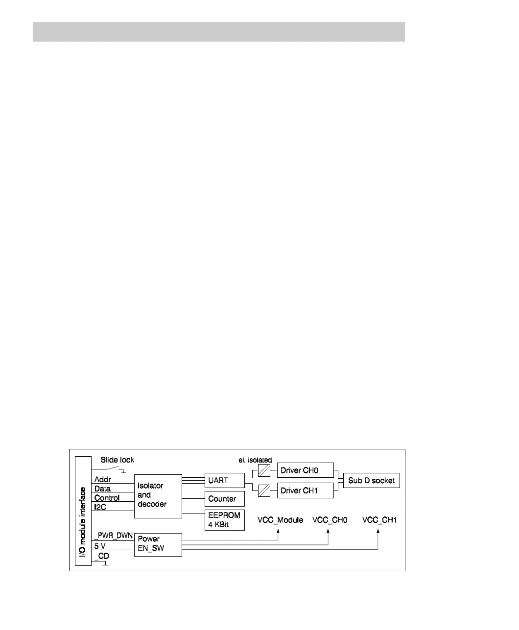
Block diagram
Fig. 7-10 FI 820F block diagram