4 Cabling the AC 800F
4-85
• Note that with this type of connection the slaves are mere slaves and
can only communicate with a master. If you want all nodes to be
able to communicate with each other, use the RS485 interface.
• When touching the terminating jumpers take the necessary ESD
protection measures. Follow the instructions given in Section 2.
• If the shield is not put on properly, neither RFI suppression nor
EMI/RFI shielding of the system can be guaranteed.
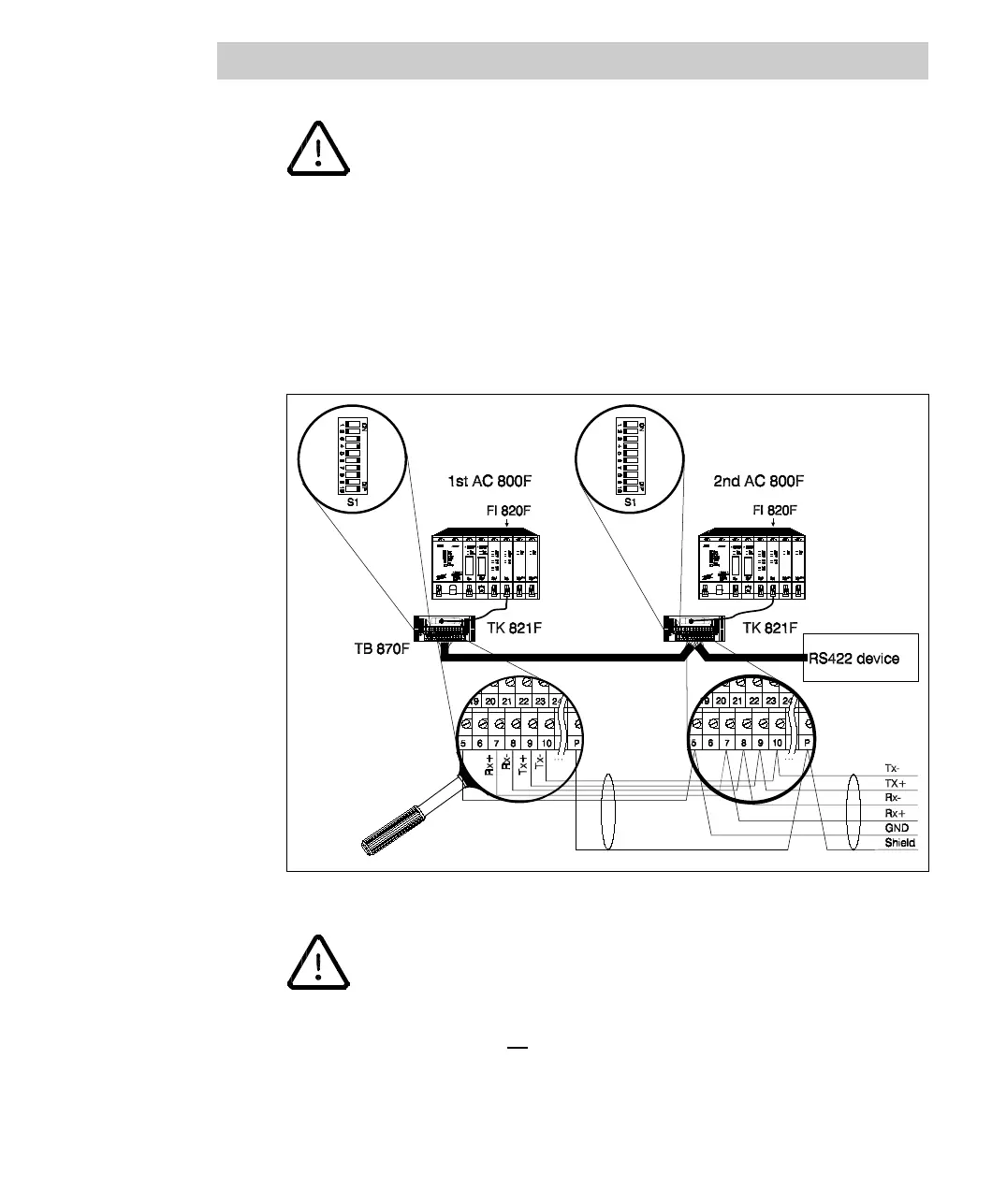
Fig. 4-62 shows redundant cabling of two AC 800F with one serial fieldbus module
each, using channel 0. Connect the external power supply, as seen in Fig. 4-59.
Fig. 4-62 Redundant cabling of two FI 820F via RS422 interfaces, using channel 0
• When working in the redundancy mode, exclusively use an
external termination with external power supply. If the module’s
termination voltage is used, the bus is not terminated properly when the
module is switched off or replaced.
• Make sure that no jumpers are set on the fieldbus modules and that
the switches on the internal terminal block TB 870F areintheOFF
position.