6 Functional Description of the Ethernet Modules
6-30
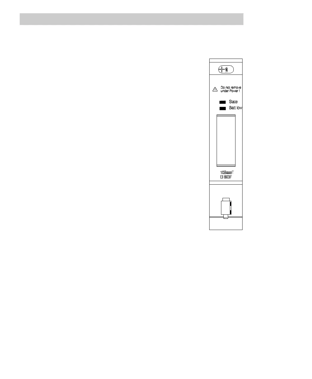
Description of the status indicators
The module EI 803F has a multicolor LED which indicates the current module state:
State LED
• Off No voltage applied, module is separated.
• Green Power supply switched on, module identified
and ready to operate according to configuration.
• Orange Power supply switched on, module identified:
- intermediate state after normal module
startup or
- configuration mode of Boot Loader (see Sec-
tion 5.4)
• Orange flashing Power supply switched on, module identified;
module not connected to a proper bus structure.
• Red Power supply switched on:
- -module not yet identified (short time, during
module startup) or
- error occurred during module test
Batt low LED
• Off Sufficient buffer battery voltage.
• Yellow Buffer battery not found or low (insufficient
voltage).
Two single-color LEDs are provided on the RJ45 connector, indicating the current
communication state. Although these LEDs are not labeled, they can be clearly identi-
fied through their color. The upper, yellow LED indicates the link state, the lower,
green LED indicates that communication is active.
10BaseT Link LED
• OFF No active link. Communication is not possible.
• Yellow static Active link. Communication is possible.
10BaseT Active LED
• Off No communication.
• Green flashing Communicating.