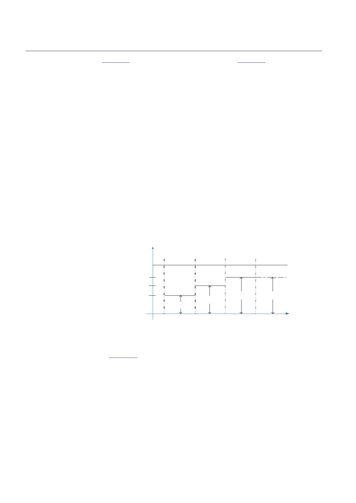
Figure 363 shows voltage dip operational regions. In Figure 362, only one voltage dip/
swell/Int set is drawn, whereas in this figure there are three sub-limits for the dip
operation. When Voltage dip set 3 is undershot, the corresponding ST_x and also the
DIPST outputs are activated. When the TRMS voltage magnitude remains between
Voltage dip set 2 and Voltage dip set 1 for a period longer than VVa dip time 2 (shorter
time than VVa dip time 3), a momentary dip event is detected. Furthermore, if the
signal magnitude stays between the limits longer than VVa dip time 3 (shorter time
than VVa Dur max), a temporary dip event is detected. If the voltage remains below
Voltage dip set 1 for a period longer than VVa dip time 1 but a shorter time than VVa
dip time 2, an instantaneous dip event is detected.
For an event detection, the OPERATE output is always activated for one task cycle.
The corresponding counter and only one of them (INSTDIPCNT, MOMDIPCNT or
TEMPDIPCNT) is increased by one. If the dip limit undershooting duration is shorter
than VVa dip time 1, VVa swell time 1 or VVa Int time 1, the event is not detected at all,
and if the duration is longer than VVa Dur Max, MAXDURDIPCNT is increased by
one but no event detection resulting in the activation of the OPERATE output and
recording data update takes place. These counters are available through the monitored
data view on the LHMI or through tools via communications. There are no phase-
segregated counters but all the variation detections are registered to a common time/
magnitude-classified counter type. Consequently, a simultaneous multiphase event,
that is, the variation-type event detection time moment is exactly the same for two or
more phases, is counted only once also for single-phase power systems.
Voltage dip set 1
Voltage dip set 2
Voltage dip set 3
Voltage
xUref
Time (ms)
0
0
VVa Dur MaxVVa dip time 3VVa dip time 1 VVa dip time 2
1.00
Instantaneous
dip
Temporary
dip
Momentary
dip
Maximum duration
dip
GUID-0D3F6D81-F905-4D8D-A579-836EF7BB6773 V1 EN
Figure 363: Voltage dip operational regions
In Figure 364, the corresponding limits regarding the swell operation are provided
with the inherent magnitude limit order difference. The swell functionality principle
is the same as for dips, but the different limits for the signal magnitude and times and
the inherent operating zone change (here, Voltage swell set x > 1.0 xUn) are applied.
Section 10 1MRS758755 A
Power quality measurement functions
684 REC615 and RER615
Technical Manual

 Loading...


