Asynchronous Transfer Mode – ATM
Page 100 Acterna ANT-5
Note 1: This section assumes that you are familiar with the functionality of the graphic
user interface. However, before proceeding you may wish to review section 4, The
SDH Access Tester application.
6.2.1 ATM Setup and Result tabs
ATM Tabbed Setup pages
Signal setup page
ATM setup page
ATM Setup Summary
Channel explorer setup page
ATM Measurement Selection
page
ATM Tabbed Result pages
ATM Cell Statistics
ATM Quality of Service
Channel Explorer results
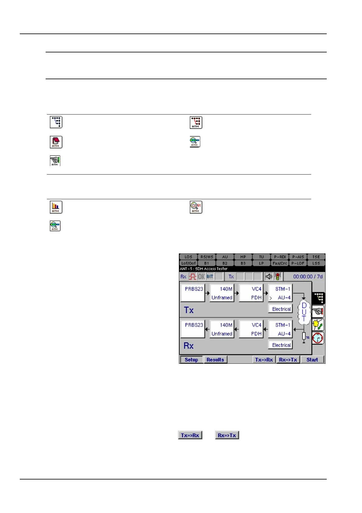
6.3 Configuring the Physical Layer
The signal structure for the particular
device or system under test has to be
configured before setting any ATM
parameters.
Following the Tx setup, this example
shows a PRBS23 pattern passing into
a 140Mbit/s Unframed PDH signal.
This is mapped into a virtual container
VC-4 which is then aligned into an
administrative unit AU-4 and finally
multiplexed into an STM-1, using an
electrical interface. See section 4.4,
Signal Structure setup page for further details on configuring the physical layer.
In most cases the user interface for the Tx is the same as the user interface for the
Rx. An exception to this rule is the ATM Header Rx, where a VCI and/or a CLP filter
can be enabled. See section 6.4.2 for further details.
Where the system under test is symmetrical, and the Tx and Rx structures are
required to be identical, time can be saved by setting up either the Tx or the Rx
structure, and then pressing either the or keys as appropriate. The
structure will be copied from Tx to Rx, or vice versa, as selected.