Introduction
Acterna ANT-5 Page 17
When the application is set up to use a Tx or Rx interface, an LED adjacent to the
appropriate external connector will be illuminated. If an Rx interface has been
selected, but has no signal detected by the application, its LED will flash.
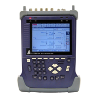
1.6 Physical layout and connectors – BN 4565/02
The ANT-5 has the following external connectors at the rear and side:
STM-n
Optical Tx, Rx
FC/PC 1310nm
and/or 1550nm
Optical Tx and Rx connectors for STM-1 or
STM-4
Note: The optical interfaces are optional.
STM-1, E4, DS3, E3
Electrical Tx, Rx
BNC, 75Ω,
nickel plated
Unbalanced electrical Tx and Rx connectors
for STM-1 and higher-order PDH payloads
E1
Tx, Rx
BNC, 75Ω,
nickel plated
Unbalanced electrical Tx and Rx connectors
for E1 PDH payload
E1
RJ48, 8-wire
(6 wires used)
Balanced 120Ω electrical connector for E1
PDH payload
Ext Clk input
BNC, 75Ω,
nickel plated
Unbalanced electrical clock input for Tx at
2048 kbit/s or 2048 kHz
COM 1
RS232C
D type 9-way
Male
V.24 serial port
19V DC power
3A
2.1mm 19V Power supply input. For use with type
PPS-2 only
<
…
> RJ45
10 base T – TCP/IP Ethernet port