Introduction
Acterna ANT-5 Page 15
Software Version Base Software Optional Software
04.00… Repetitive BERT
APS Measurement
Pointer Analysis
Round Trip Delay
03.00… Tandem Connection Monitoring
M2101 performance analysis
1.4 Acterna ANT-5 Hardware version summary
This manual refers to three types of hardware that are differentiated as follows:
Version Description
BN4565/03
(label on reverse)
STM-16 units. A T1 and ECL interface are located on the right
side of the unit. Included in this build is optical power
measurement functionality, NRZ STM monitor port, E1 Hi-Z input
and a PDH T1 Interface. See section 1.7 and 4.22 for further
details.
BN4565/02
(label on reverse)
A CompactFlash card slot is situated on the right of the unit. See
section 1.6 for further details.
BN4565/01
A PC Card slot situated on the left of the unit. See section 1.5 for
further details.
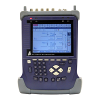
1.5 Physical layout and connectors – BN4565/01
The ANT-5 has the following external connectors at the rear and side:
STM-n
Optical Tx, Rx
FC/PC 1310nm
and/or 1550nm
Optical Tx and Rx connectors for STM-1 or
STM-4
Note: The optical interfaces are optional.
STM-1, E4, DS3, E3
Electrical Tx, Rx
BNC, 75Ω,
nickel plated
Unbalanced electrical Tx and Rx connectors
for STM-1 and higher-order PDH payloads
E1
Tx, Rx
BNC, 75Ω,
nickel plated
Unbalanced electrical Tx and Rx connectors
for E1 PDH payload
E1 RJ48, 8-wire
(6 wires used)
Balanced 120Ω electrical connector for E1
PDH payload
Ext Clk input
BNC, 75Ω,
nickel plated
Unbalanced electrical clock input for Tx at
2048 kbit/s or 2048 kHz