Asynchronous Transfer Mode – ATM
Page 102 Acterna ANT-5
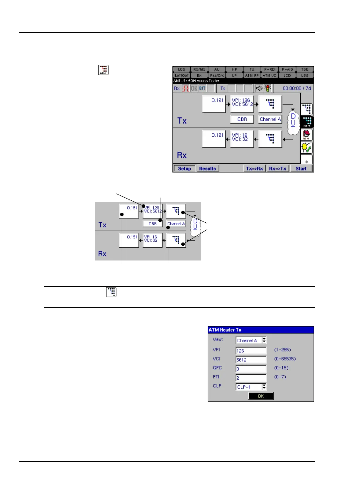
6.4.1 The ATM structure
Select either the tab from the right
of the screen, or the ATM icon from
the structure setup page. A graphic
similar to the one on the right will be
displayed. The ATM structure can
now be configured.
In this diagram Channel A is
displayed as the channel under test.
The Channel A panel is used to
switch to view other channel setups,
(assuming concurrent channels have
been selected). See section 6.4
Select to view signal
structure setup
Select to view
Channel B setup
ATM Header
ATM SDU
ATM Service
Contract Attributes
Note: Use the tab or icon to switch to the physical signal structure layer at any
time.
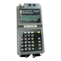
6.4.2 ATM Header Tx
Sets the parameters for the ATM Header. The
Virtual Path Indicator VPI and Virtual Channel
Indicator VCI are used for switching purposes.
VPI identifies the cell belonging to a particular
path, whilst the VCI identifies the cell belonging
to a particular channel.
Four bits are used for Generic Flow Control GFC.
These bits control the flow of data between the
user and the network. GFC can only be set if UNI is selected as the Interface. See
section 6.4, Configuring the ATM Layer for further details.