The SDH Access Tester application
Page 64 Acterna ANT-5
The transmitter offset can be adjusted in steps of 0.1ppm by pressing the required
offset firm key, or offset in increments of 1.0 by pressing and holding down the
appropriate firm key.
The range over which the offset can be skewed depends on the initial value set in the
Interface Setup Tx panel. For example, if the test starts with a negative value, its
associated range will be from –100.0 to –0.1. However, if the test starts with a positive
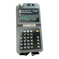
value, the range will be from 0.0 to 100.0. The following example shows the results
associated with clock offset.
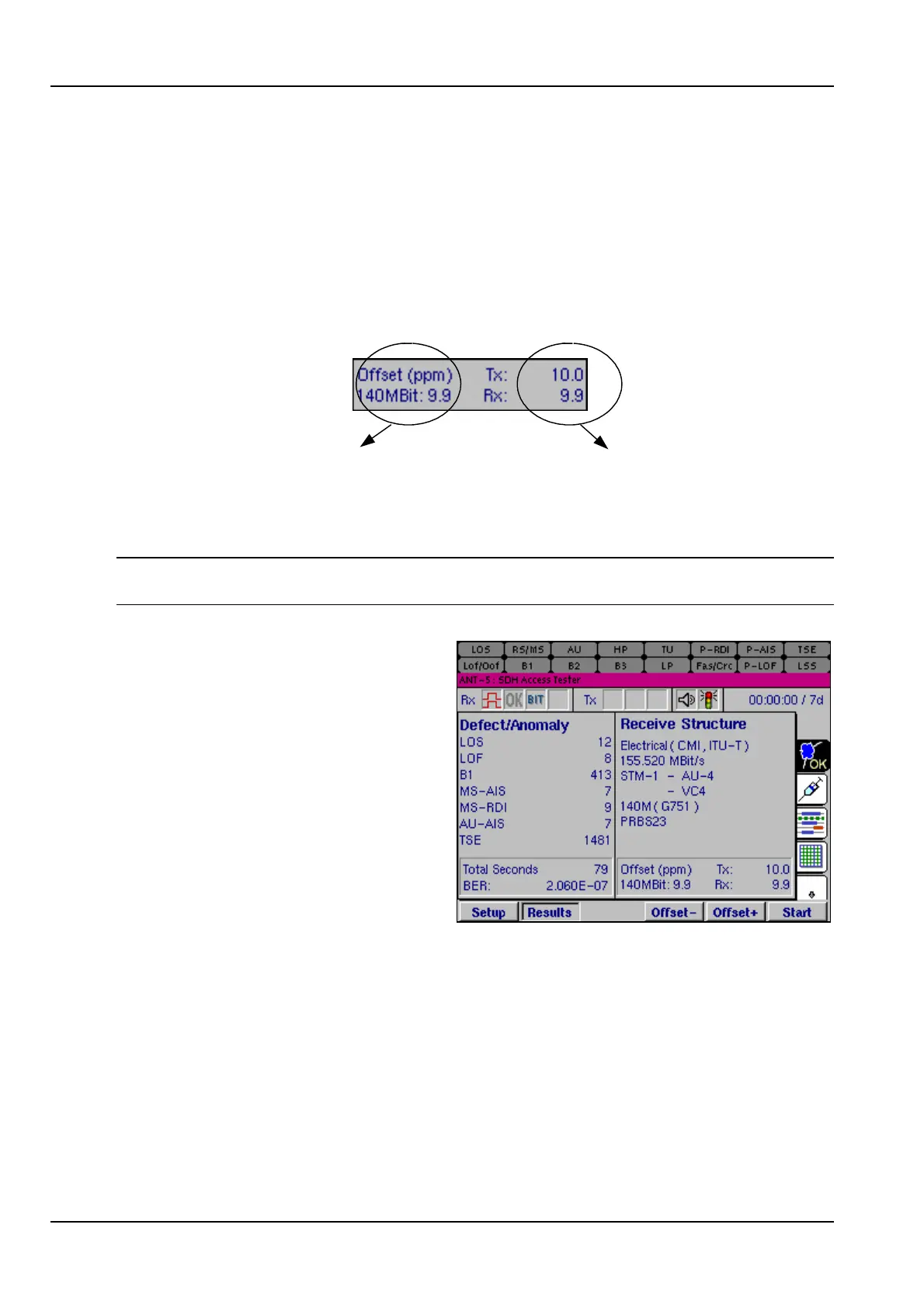
This is the Rx offset (in ppm)
of the 140Mbit tributary
carried in the VC4 being
tested
These are the Tx and Rx
offsets (in ppm) for the Line
Rate, for example
155.520Mbit/s
Note: The offset firm keys will be greyed out when the value reaches the end of its
range.
The Defect/Anomaly list contains the
total number of seconds during which
each defect has been detected and
the total count of each anomaly which
has occurred.
The defects and anomalies are listed
in order of importance and priority.
For further details, see Appendix D –
SDH and PDH information.
4.11 Injection
A wide range of anomalies and defects can be injected into the transmitted signal,
depending upon the signal structure selected.
If an SDH line interface is selected, the relevant SDH anomalies and defects can be
injected. If a PDH test signal is injected into the SDH virtual container, the relevant
PDH anomalies and defects can also be injected. If, however, a PDH line interface is
selected, then only the PDH anomalies can be injected.
In addition to injecting into either the SDH or PDH structures, injection of TSEs (bit
errors) into the relevant payload is also available using the Transmit Pattern.