Introduction
AdeptModules Instruction Handbook, Volume 1: Adept MV Controller Interface, Rev. A 137
C.1 Introduction
This appendix gives an example of a three axis AdeptModules system “SPEC” file. Don’t
assume that it will work in all applications.
C.2 Sample SPEC File
Table C-1 shows the contents of a sample specification file that was created for an
AdeptModules LMMV X/Y/Z system with three axes.
In addition to specification information, the file also contains some computed values that
were automatically derived from the robot specification data.
A typical data section within the specification data file looks like this:
DATA 61 ; COUNTS PER JOINT TRAVEL
711.1111, 444.4444, 533.3333,
277.7778
Following the word “.DATA” is the data section number, 61. This number indicates to the
motion system where the data is to be stored in system memory. The data section number
is followed by a descriptive comment about the data section. Ensuing lines contain the
values as stored in system memory. In this case, the values are stored in joint order. Other
data sections, such as link dimensions, are stored in an order particular to the robot. This
sample specification file shows the data for:
.HEADER Robot Specification Data Version 1.3
; Created by SPEC 12.1B1 on 12-May-97 08:17:35
; Software: 12.1 83-100 (Edit D5, 21-Feb-1997, Development Test)
; Controller: 3305-678 0
; Servo rate: 1000 Hz
; Processor 1: 0.2 1-5 4Mb
Robot 1: 400-1 0-0 32
Title: "AdeptModules X/Y/Z Robot."
.DATA_SECTION
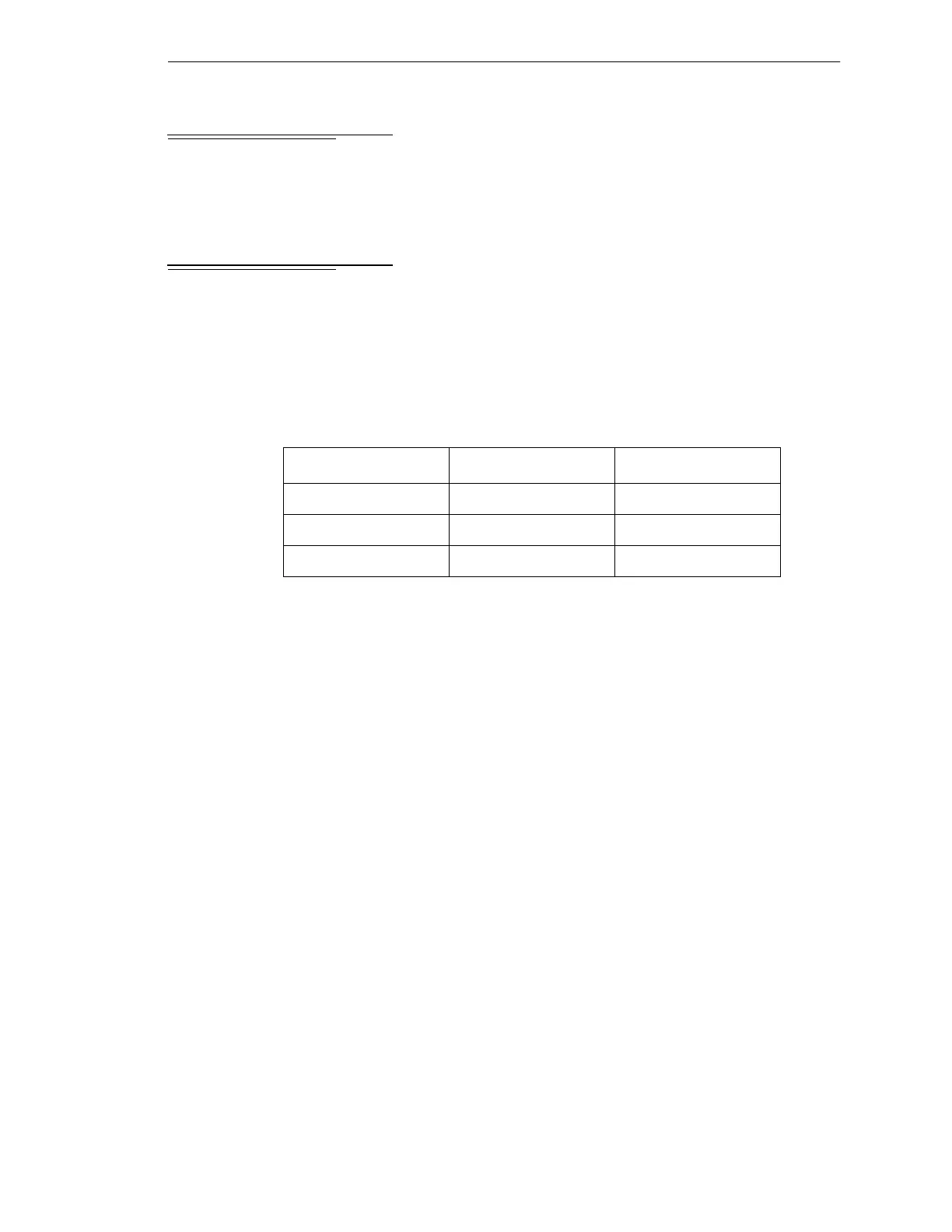
Table C-1. AdeptModules Specifications for Sample Spec. File
Axis AdeptModule Part Number
X-Axis 800mm H-Module 90400-10080
Y-Axis 550mm M-Module 90400-20055
Z-Axis 230mm Sz-Module 90400-40023
Artisan Technology Group - Quality Instrumentation ... Guaranteed | (888) 88-SOURCE | www.artisantg.com