Chapter 2 - Installation
42 AdeptModules Instruction Handbook, Volume 1: Adept MV Controller Interface, Rev. A
• PENDANT: connector for attaching the Manual Control Pendant (MCP) to the
front panel. In order to enable High Power, either the MCP or the supplied
pendant jumper plug must be connected.
Installing the External Front Panel (VFP)
The VFP can be mounted in a standard 19-inch equipment rack. See Figure 6-5 on page
115 for dimensions. Since the back of the VFP is open, make sure that it is securely
mounted and that electronic components on the back side of the panel are protected from
contact by users or other equipment. Mount the VFP in the same enclosure as the
controller, or in a separate, protected enclosure. See Table 2-1 for enclosure requirements.
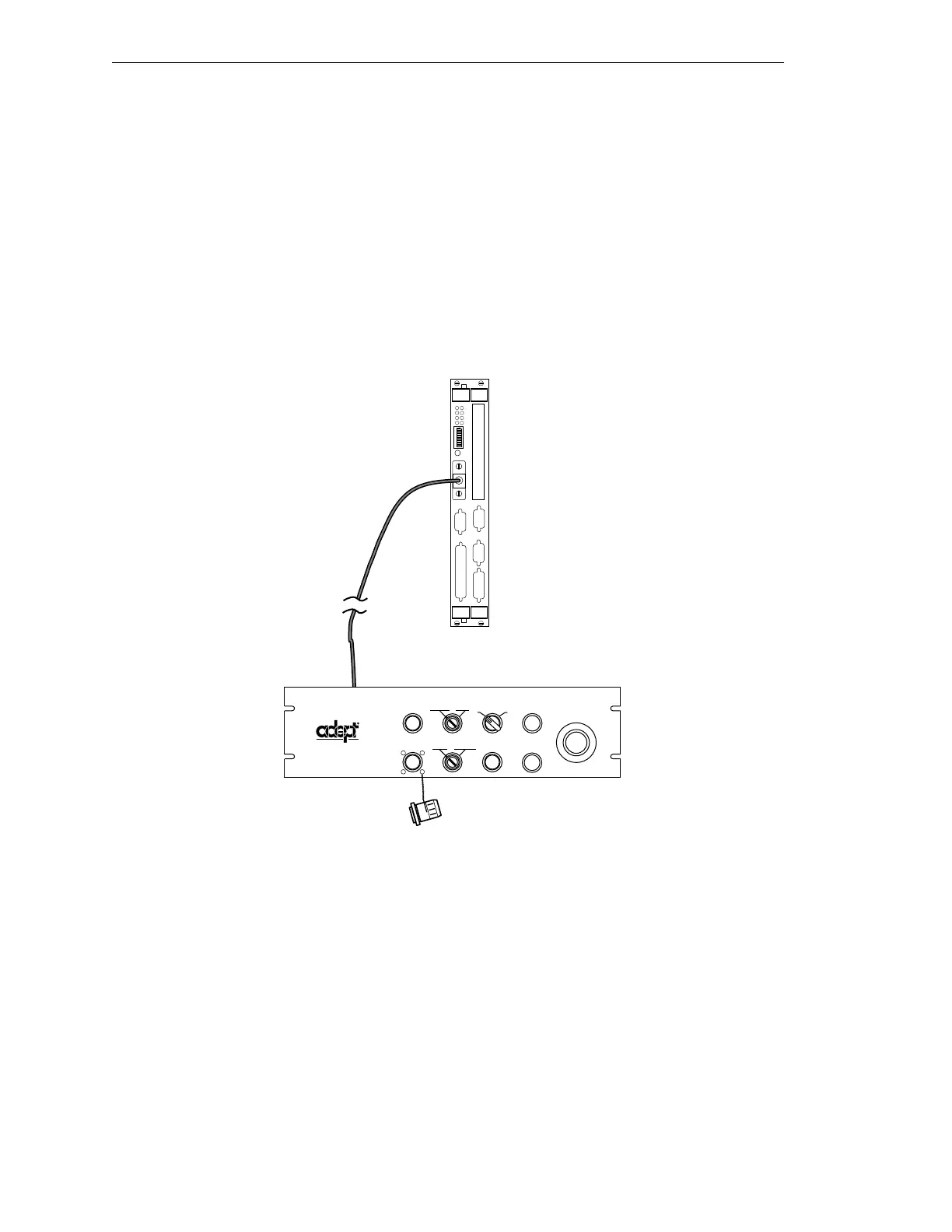
See Figure 2-7 as you follow the procedures listed below.
Figure 2-7. External Front Panel (VFP) Installation
1. Turn off the power switch on the front of the Adept MV controller.
2. Remove the FP/MCP bypass plug from the FP/MCP connector on the SIO
module.
3. Locate the 2-meter Front Panel cable that comes with the VFP. Plug one end into
the FP/MCP connector on the SIO module. Plug the other end into the 27-pin
D-Sub connector on the back of the VFP. Tighten the thumbscrews on both
connectors.
4. If you are not using an MCP, install the MCP bypass plug in the MCP connector of
the VFP. If you are using an MCP, refer to page 55.
1
2
3
4
F
P
/
M
C
P
D
R
I
V
E
A
6
7
85
ON
2
3
41
OK
SIO
R
S
2
3
2
R
S
2
3
2
R
S
2
3
2
I
/
O
2
4
V
1
0
0
m
A
E
T
H
E
R
N
E
T
OK
ESTOP
ACC V
SCSI
RESET
VFP
SIO
NETWORK
HIGH POWER
ON/OFF
PROGRAM
RUNNING
SYSTEM
POWER
PROGRAM
START
LAMP
TEST
PENDANT
MANUAL AUTO
EMERGENCY STOP
I
O
®
LOCAL
Artisan Technology Group - Quality Instrumentation ... Guaranteed | (888) 88-SOURCE | www.artisantg.com