Chapter 2 - Installation
54 AdeptModules Instruction Handbook, Volume 1: Adept MV Controller Interface, Rev. A
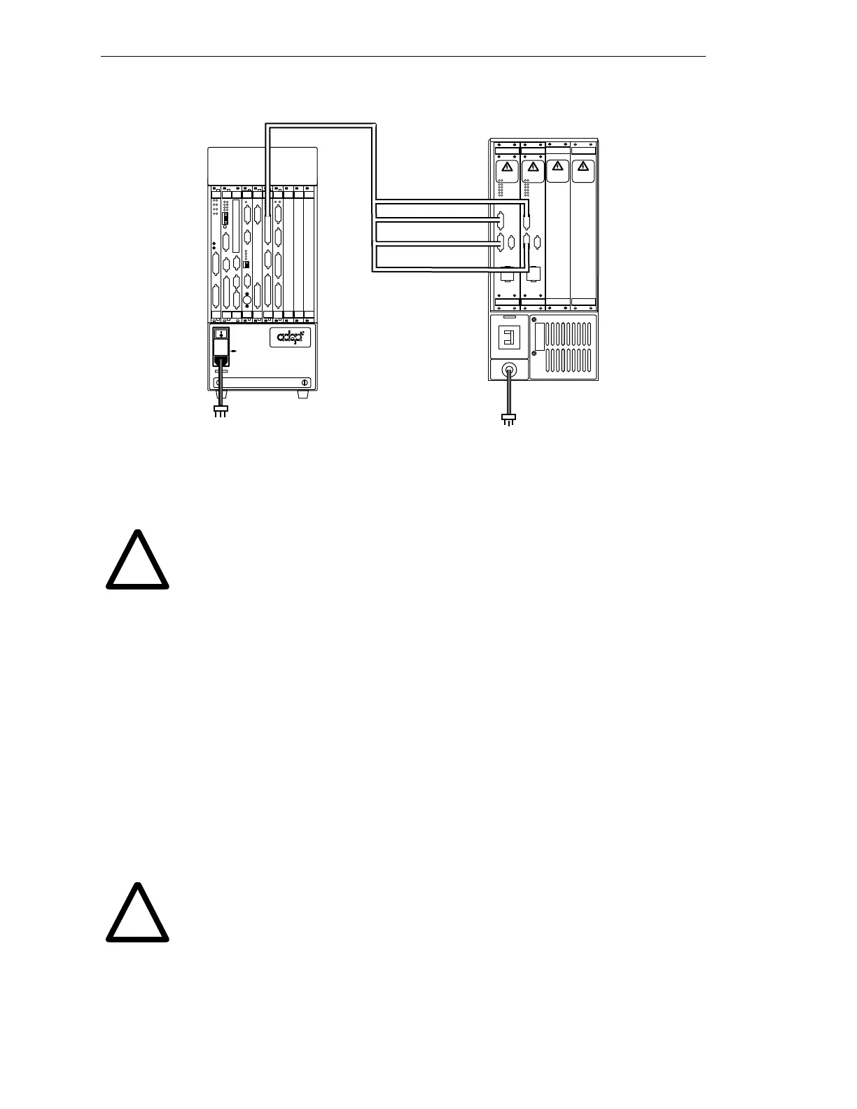
Figure 2-15. Connecting the PA-4 Power Chassis to the MV Controller
3. Verify that all connectors are secure and fully inserted and installed in the correct
location.
WARNING: Verify that all connectors are fully inserted and screwed
down. Loose connectors could cause unexpected AdeptModules motion.
Also, a connector can be pulled out or dislodged unexpectedly.
Installing Signal Cables: MV Controller to Signal Interface Box
The EJI-to-Signal Interface Box cable is the interconnect between the controller and the
Signal Interface Box. This cable assembly has a 50-pin D-sub connector on one end (for the
EJI) and a 50-pin D-sub connector on the other end (for the Signal Interface Box).
1. Connect the cable end labeled EJI to the connector marked Arm Signal (lower
D-sub connector) on the EJI module.
2. The other end of the cable with the 50-pin D-sub connector must be connected to
the Signal Interface Box connector labeled “Arm Signal”.
3. Verify that all connectors are secure and fully inserted and installed in the correct
location.
WARNING: Verify that all connectors are fully inserted and screwed
down. Loose connectors could cause unexpected AdeptModules motion.
Also, a connector can be pulled out or dislodged unexpectedly.
NOTE: For the differences in connecting the Adept 550 Robot to the
Adept PA-4 Power Chassis, refer to the Adept 550 Instruction Handbook
Rev. A. Chapter 2, Figure 2-13.
adept
technology, inc.
DO NOT REMOVE THIS PANEL UNLESS
SYSTEM POWER IS OFF AND AMPLIFIER
HIGH VOLTS LED(S) IS COMPLETELY
EXTINGUISHED. DO NOT OPERATE
WITHOUT THIS PANEL INSTALLED.
DO NOT REMOVE THIS PANEL UNLESS
SYSTEM POWER IS OFF AND AMPLIFIER
HIGH VOLTS LED(S) IS COMPLETELY
EXTINGUISHED. DO NOT OPERATE
WITHOUT THIS PANEL INSTALLED.
PWM ON
LOW VOLTS ON
OPEN CKT FAULT
HV SAG/OVER TEMP
HIGH VOLTS ON
SHORT FAULT
A
M
P
L
I
F
I
E
R
C
O
N
T
R
O
L
B+ AMP
M
O
T
O
R
P
O
W
E
R
O
U
T
P
U
T
B1
B2
B1 B2
DO NOT REMOVE OR INSTALL THIS
MODULE UNLESS HIGH VOLTS LED
IS COMPLETELY EXTINGUISHED.
T
E
A
C
H
R
E
S
T
R
I
C
T
®
V
I
D
E
O
B
U
S
C
A
M
E
R
A
S
/
S
T
R
O
B
E
S
VIS
P
O
I
N
T
E
R
1
2
3
4
ON
2
3
41
V
I
D
E
O
B
U
S
M
O
N
I
T
O
R
KEYBOARD
OK
VGB
I
N
P
U
T
S
O
U
T
P
U
T
S
I
N
P
U
T
S
O
U
T
P
U
T
S
DIO
FAIL PASS
1
2
3
4
F
P
/
M
C
P
D
R
I
V
E
A
6
7
85
ON
2
3
41
OK
SIO
R
S
2
3
2
R
S
2
3
2
R
S
2
3
2
I
/
O
2
4
V
1
0
0
m
A
E
T
H
E
R
N
E
T
OK
ESTOP
ACC V
SCSI
RESET
R
S
4
2
2
R
S
2
3
2
/
T
E
R
M
040
STP
SCR
C
VME
SF
A
B
D
RESET
ABORT
#1
#2
HPE
2
4
6
ES
1
3
5
VJI
AMPLIFIER
SIGNAL
ARM
SIGNAL
BELT
ENCODER
WARNING:
FOR CONTINUED PROTECTION
AGAINST RISK OF FIRE,
REPLACE ONLY WITH SAME
TYPE AND RATING OF FUSE.
USE ONLY WITH
250V FUSES
~100-240V
50/60HZ
5AT
PWM ON
LOW VOLTS ON
OPEN CKT FAULT
HV SAG/OVER TEMP
HIGH VOLTS ON
SHORT FAULT
A
M
P
L
I
F
I
E
R
C
O
N
T
R
O
L
B+ AMP
M
O
T
O
R
P
O
W
E
R
O
U
T
P
U
T
B1
B2
B1 B2
DO NOT REMOVE OR INSTALL THIS
MODULE UNLESS HIGH VOLTS LED
IS COMPLETELY EXTINGUISHED.
T
E
A
C
H
R
E
S
T
R
I
C
T
Axis 1
Axis 2
Axis 3
Axis 4
!
!
Artisan Technology Group - Quality Instrumentation ... Guaranteed | (888) 88-SOURCE | www.artisantg.com