Chapter 4 - Commissioning the System
94 AdeptModules Instruction Handbook, Volume 1: Adept MV Controller Interface, Rev. A
WARNING: Impact Hazard!
In Automatic mode no personnel are allowed in the workcell. The
AdeptModules can move at high speeds and exert considerable forces.
Calibration involves limited AdeptModules motion. Observe all safety
precautions.
1. Set the VFP operating keyswitch to the AUTO position and verify that the other
keyswitch is in the LOCAL position. If necessary, reenable High Power.
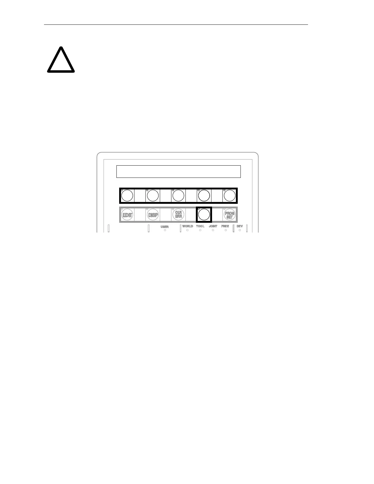
2. Press the CMD soft button to display the MCP functions (see Figure 4-3).
3. Ensure that none of the joints are positioned at the end of their travel, covering the
sensors. This will cause calibration errors. Position the joints in the middle of their
travel range.
Figure 4-3. Command (CMD) Function Button
4. Press the soft button below the text CALIB in the display to start calibration.
Changing Calibration Direction
AdeptModules calibrate by default toward the motor end of the module. By modifying
SPEC parameters and teaching calibration, the direction of travel for calibration can be
changed. The following steps should be used as a guideline for changing the parameters.
Adept assumes that the user has a working knowledge of SPEC and a general
understanding of kinematics before performing this procedure.
The direction of travel for calibration can be changed by changing the sign of the “Speed
and Direction of Search” parameter and then reteaching calibration.
1. Load and execute SPEC.V2 (see instructions on page 91 ).
2. Select “Edit Robot Specifications” from the main menu.
3. Select “Edit Motor Calibration Parameter” from the submenu.
4. Select and change the “Speed and Direction for Search” parameter sign.
5. Select “Teach calibration specs”.
SPEC will prompt in the following :
Before teaching calibration, you should:
1. Have properly tuned all motors.
!
CMD
AUTO
START
CALIB
STORE
ALL
CMD1
CMD2
Artisan Technology Group - Quality Instrumentation ... Guaranteed | (888) 88-SOURCE | www.artisantg.com