Overview of Safety System
AdeptModules Instruction Handbook, Volume 1: Adept MV Controller Interface, Rev. A 79
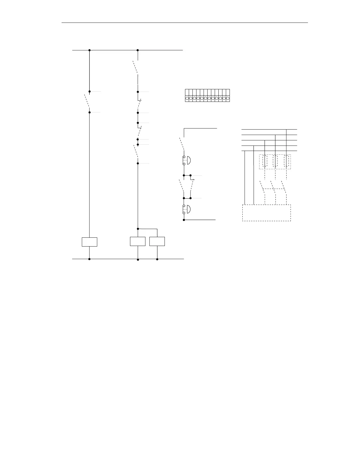
Figure 3-3. E-Stop Circuitry with Additional Safety Equipment
PE
PE
N
N
L3
L3
L2
L2
L1
L1
K3*
F1
PA-4 Power Chassis
TB.1
TB.5
TB.6
TB.7
TB.8
TB.9
TB.10
Pin 44 on digital I/O
connector
on SIO Module
Pin 42 on digital I/O connector
on SIO Module
TB.2
System Power
Switch
Operating
Mode
Switch
Safety Gate
(Muted in
Manual Mode)
User External
E-Stop Device
User External
E-Stop Device
External E-Stop Input
MCP E-STOP
VFP E-STOP
TB.3
TB.4
MCP Hold-to-Run
K1
K2
K3
K1
K2
1211
12
3
4
5
678
910
Terminal block on external
Front Panel
User-supplied 24 V (or 12 V)
Ground
(*) The implementation of the K3 High Power contactor is not necessary
to achieve Category 1 operation, per EN 954.
Note: This drawing is ONLY an example for the implementation of additional
safeguards.
Artisan Technology Group - Quality Instrumentation ... Guaranteed | (888) 88-SOURCE | www.artisantg.com