Chapter 2 - Installation
66 AdeptModules Instruction Handbook, Volume 1: Adept MV Controller Interface, Rev. A
2.19 Additional Power Chassis Information
B
+
Amplifier Module Overview
The B
+
Amplifier module is a plug-in module that contains the circuitry and amplifying
components to drive two AdeptModules motors. In a typical AdeptModules system, there
is one B
+
Amplifier module in the Adept PA-4 power chassis. This Amp module will drive
the motors for two AdeptModules.
NOTE: AdeptModules require a Dual B
+
amp or newer version of the
PA4 power chassis
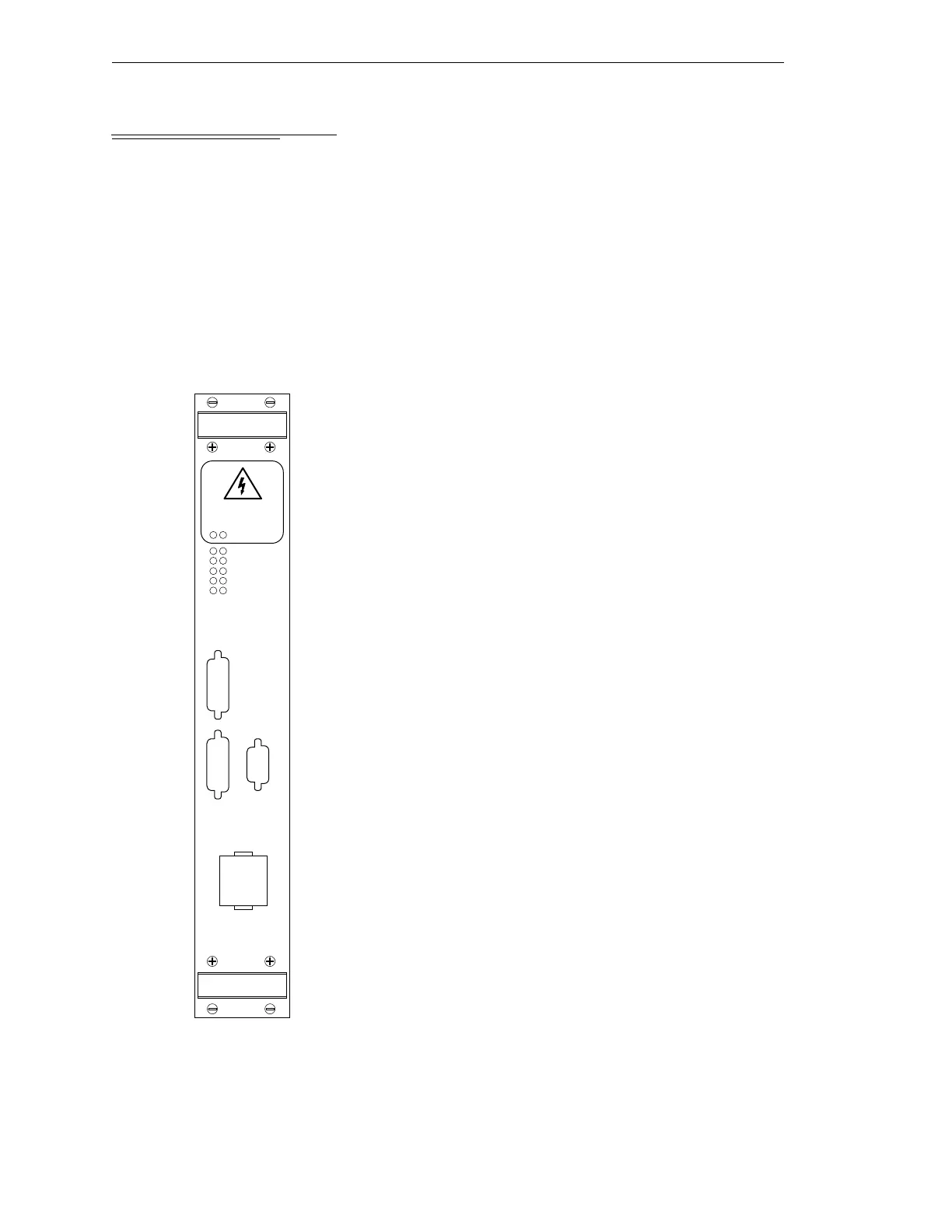
Connectors and Indicators
➊ Status LEDs. The left-hand column of LEDs is for the first
motor controlled by this module; the right-hand column is
for the second motor controlled by this module. A lit LED
indicates one of the following conditions:
High Volts On indicates the high voltage to the amps is
turned on.
PWM On indicates that current servo is on. It does not go on
until calibration is complete.
Low Volts On indicates the low voltage supply in the power
chassis is on.
Note: the three LED pairs below indicate faults and are
visible momentarily before the system turns off.
Open Ckt Fault indicates that an open circuit in the motor
leads has been detected.
Short Fault indicates that an over-current in the motor leads
has been detected.
➋ Amplifier Control connector – the EJI-to-Amp cable connec-
tors are installed here.
Teach Restrict connector – the Teach Restrict-to-B+ Amp
cable is installed here.
➌ Motor Power Output connector – the Amp-Brake-out cable is
installed here.
PWM ON
LOW VOLTS ON
OPEN CKT FAULT
HV SAG/OVER TEMP
HIGH VOLTS ON
SHORT FAULT
A
M
P
L
I
F
I
E
R
C
O
N
T
R
O
L
B+ AMP
M
O
T
O
R
P
O
W
E
R
O
U
T
P
U
T
B1
B2
B1 B2
DO NOT REMOVE OR INSTALL THIS
MODULE UNLESS HIGH VOLTS LED
IS COMPLETELY EXTINGUISHED.
T
E
A
C
H
R
E
S
T
R
I
C
T
❶
❷
❸
Artisan Technology Group - Quality Instrumentation ... Guaranteed | (888) 88-SOURCE | www.artisantg.com