Signal Interconnection Installation
AdeptModules Instruction Handbook, Volume 1: Adept MV Controller Interface, Rev. A 51
System Cable Lengths
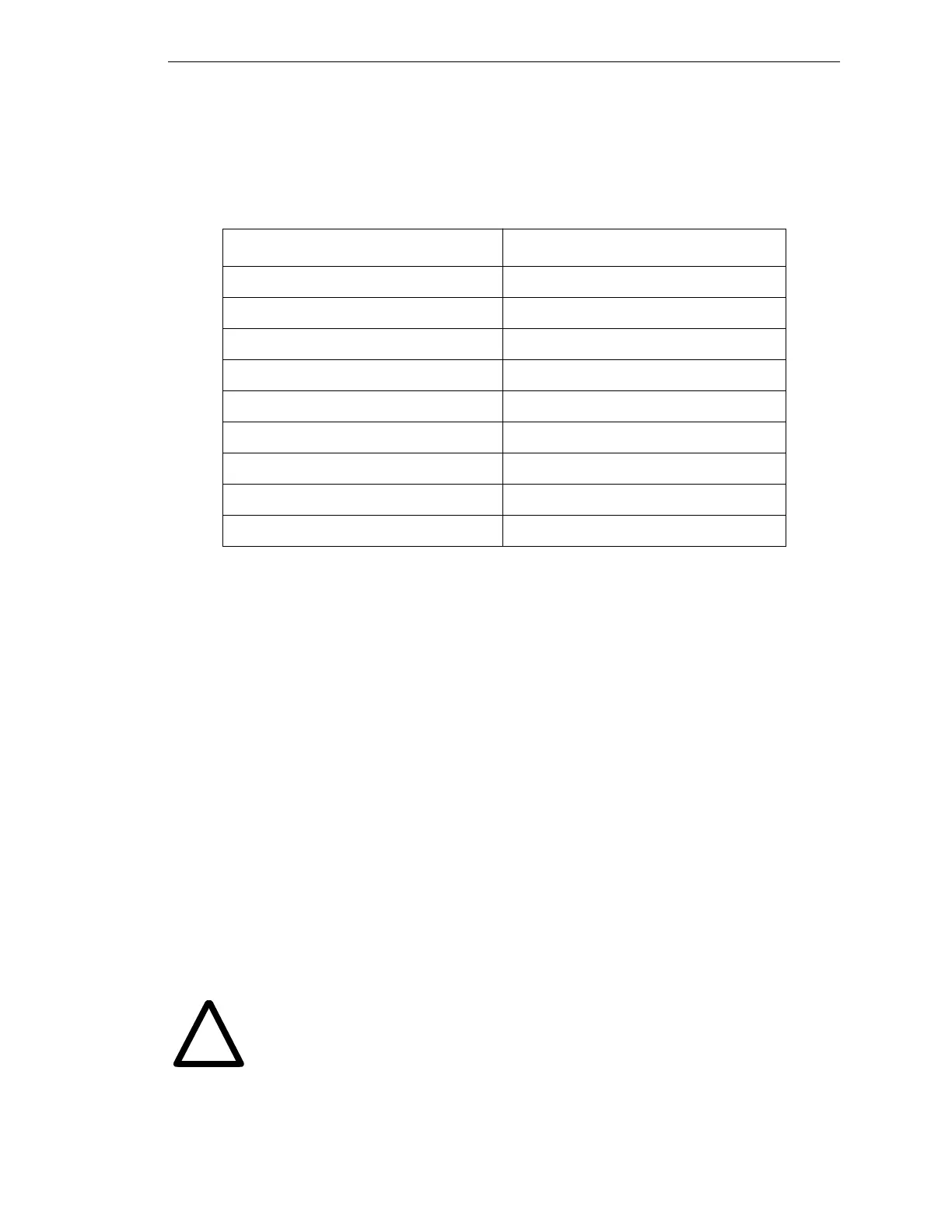
Table 2-6 describes the standard cable lengths.
Table 2-6. System Cable Lengths
Connecting the AdeptModules to the Power Chassis
The cable between the AdeptModule Interface cable and power chassis is called the Amp
Breakout cable. Both ends of the Amp Breakout cable have Molex connectors. One end of
the cable is connected to the AdeptModule Interface cables and the opposite end of the
cable is connected to the power amplifier (see Figure 2-13). Two AdeptModules can be
connected to one Dual B
+
amp using one Amp Breakout Cable.
1. Connect the Amp Breakout Cable to the AdeptModule Interface cable. Snap the
two Molex connectors together.
2. Connect the other end of the Amp Breakout Cable to the matching connectors on
the B+ Amp modules marked “Motor Power Output”.
3. Connect the motor power barrel connector to the main connector on the
AdeptModules and tighten securely.
4. Repeat these steps for each additional Module.
NOTE: The system integrator must add adequate strain relief for the Amp
Breakout cable connectors at the amplifier modules. The connectors that
join the Amp Breakout cable and the Interface cable are designed to be
inside a cabinet.
WARNING: Verify that all connectors are secure and fully inserted. Loose
connectors could cause unexpected AdeptModules motion.
Cable Length
AdeptModules Interface Cable 3 m (9.8 ft), 6m (19.7 ft), 15m (49.2 ft)
EJI-to-Signal Interface Box Cable 1.5 m (5 ft)
EJI-to-Amps Cable 1 m (3.28 ft)
Amp Breakout Cable 1.5 m (5 ft)
Front Panel Cable (SIO-to-VFP) 2 m (6.5 ft)
PA-4 Power Cord 2.9 m (9.5 ft)
SIB Power Cord 2.9 m (9.5 ft)
MV Controller Power Cord 2.9 m (9.5 ft)
MCP Cable 1.66m (5.45 ft)
!
Artisan Technology Group - Quality Instrumentation ... Guaranteed | (888) 88-SOURCE | www.artisantg.com