Overview of Safety System
AdeptModules Instruction Handbook, Volume 1: Adept MV Controller Interface, Rev. A 75
Output Signals
The digital I/O connector handles output signals 0001 to 0008. Refer to Table 3-3 for
output specifications. The locations of the signals on the connector are shown in Table 3-4.
The SIO provides separate + and – connections for each channel (no internal common
connections). This allows you the choice of wiringfor current-sourcing or current-sinking
mode as required.
Each output channel (circuit) should be connected to only one output device. Each output
circuit is short-circuit protected.
CAUTION: The above specifications for the digital inputs and outputs on
the SIO module are different from the specifications for a DIO module.
Specifically, the SIO output current is limited to 100 mA per channel,
whereas the DIO output is rated at 400 mA.
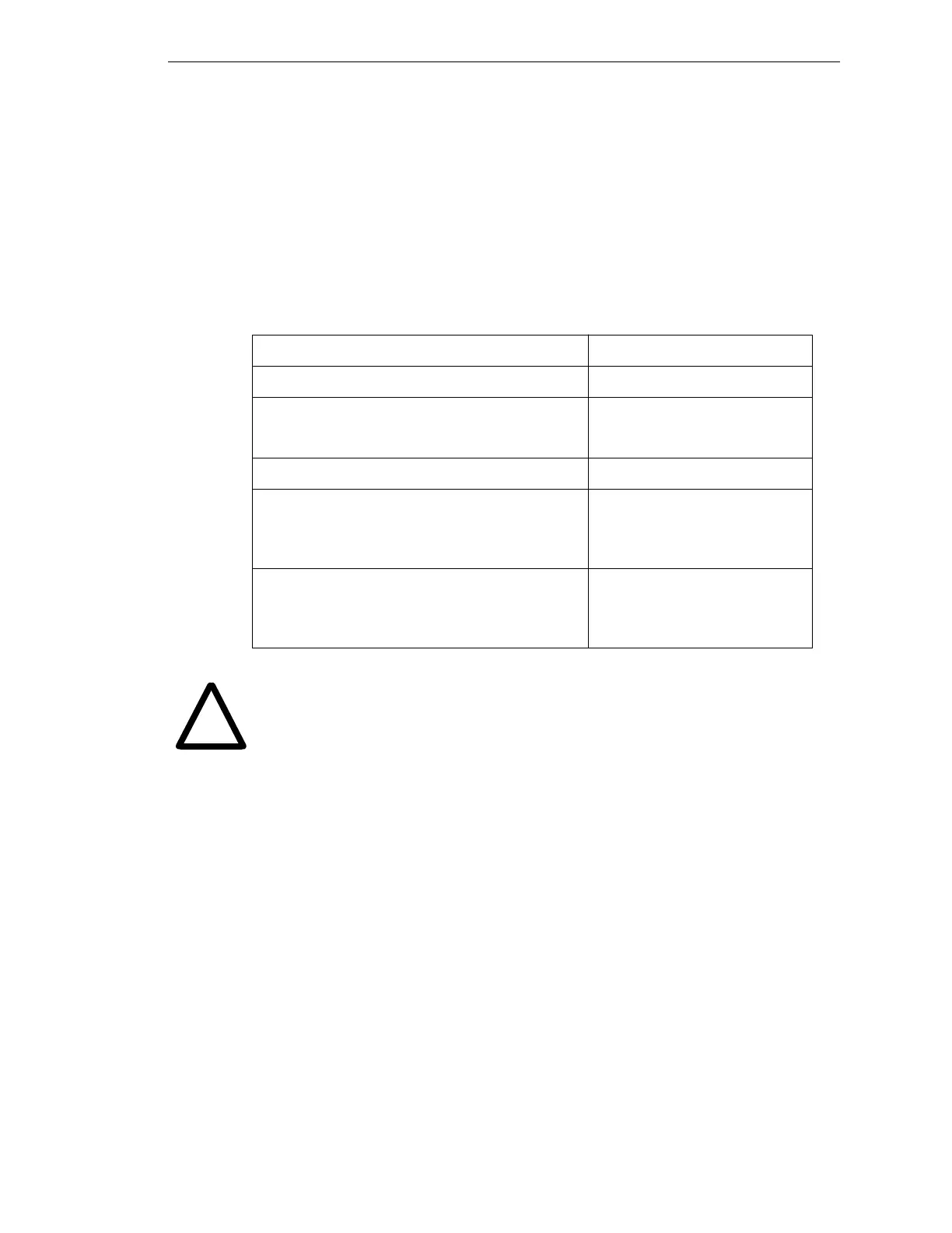
Table 3-3. DIO Output Specifications (SIO module)
Operating voltage range 0 to 24 VDC
Operational current range, per channel I
out
≤ 100 mA
V
drop
across output in on condition V
drop
≤ 0.85 V at 100 mA
V
drop
≤ 0.80 V at 10 mA
Output off leakage current I
out
≤ 600 µA
Turn on response time (hardware)
Software scan rate/response time
3 µsec maximum
16 ms scan cycle/ 32 ms max
response time
Turn off response time (hardware)
Software scan rate/response time
200 µsec maximum
16 ms scan cycle/ 32 ms max
response time
!
Artisan Technology Group - Quality Instrumentation ... Guaranteed | (888) 88-SOURCE | www.artisantg.com