Chapter 2 - Installation
58 AdeptModules Instruction Handbook, Volume 1: Adept MV Controller Interface, Rev. A
Connecting AC Power to the MV-5/10 Controller
The Adept MV Controller can operate at two different voltage settings. The identification
(ID) label identifies the model, serial numbers, the voltages and the current ratings of the
controller. The label is located on the left side of the controller chassis. A smaller serial
number label is also located on the front of the chassis above the On/Off switch. Always
have this serial number available when you call Adept Customer Service for technical
support.
The Adept MV-5 and MV-10 controllers have auto-ranging power supplies that operate at
either 100-120 VAC or 200-240 VAC single phase. The Adept MV-19 controller operates at
either 100-120VAC or 200-240 VAC single phase. MV-19 controllers are shipped from the
factory set to 200-240 VAC single phase. Contact Adept Customer Service for details on
changing to 100-120 VAC configuration (refer to Table 2-8).
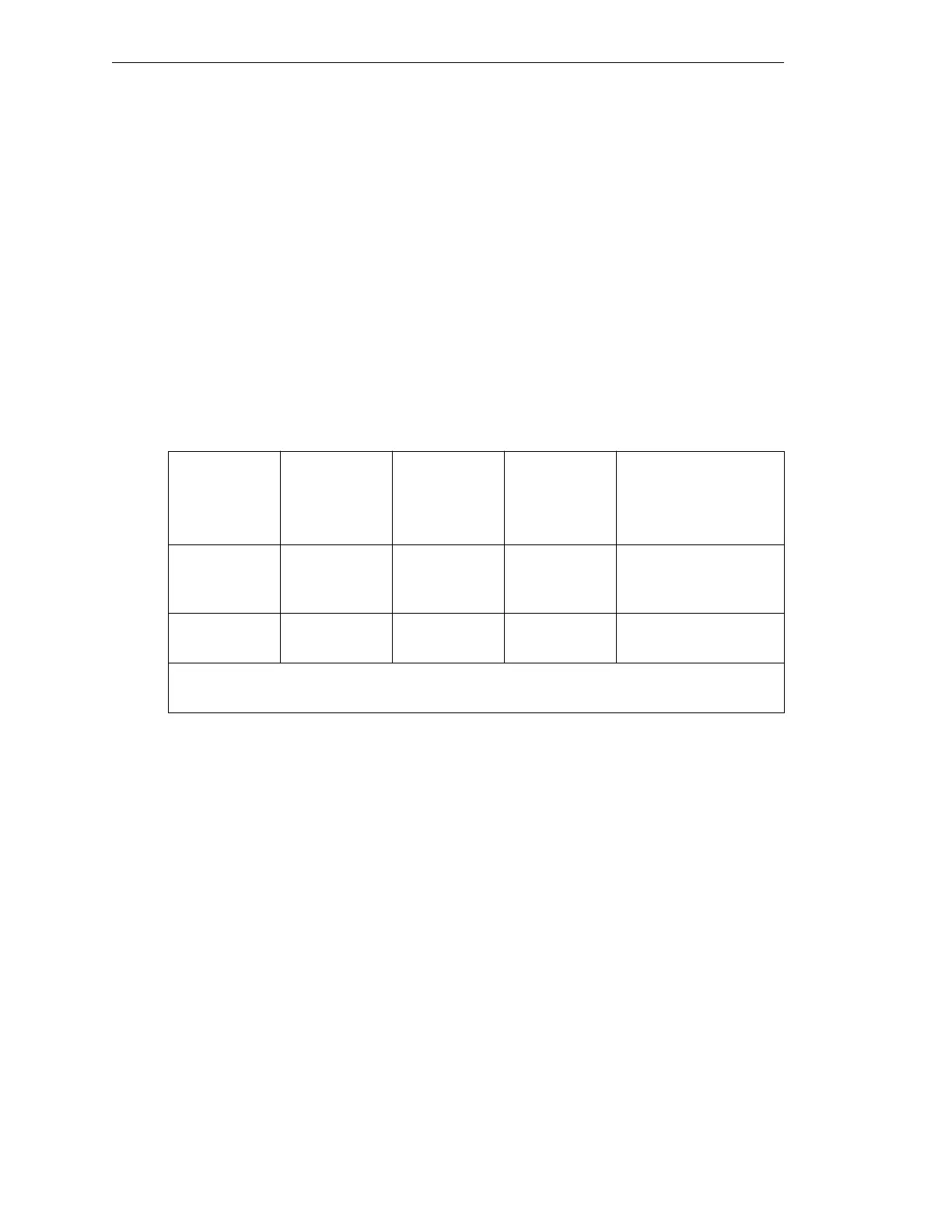
AC Power Requirements
Table 2-8. Adept MV Controller Power Requirements
Power Entry Module
The power entry module is located at the lower left side of the controller front panel (see
Figure 2-18). It contains:
• the On/Off power switch (
I = On, o = Off)
• the AC power cord socket
• the two incoming AC line fuses, rated at 10 amps
a
The maximum interruption time (operating voltage below specification) tolerated by the
controller is 16 milliseconds.
Nominal
Voltage
Range
Frequency/
Phasing
Minimum
Operating
Voltage
a
Maximum
Operating
Voltage
Recommended
External Circuit
Breaker
(user-supplied)
200V to 240V
(Factory
Setting)
50-60 Hz,
1-phase
180V 260V 10 amps
100V to 120V 50-60Hz,
1-phase
90VAC 132VAC 10 amps
Power to the Adept MV controller and PA-4 power chassis must come from a single
source.
Artisan Technology Group - Quality Instrumentation ... Guaranteed | (888) 88-SOURCE | www.artisantg.com