Chapter 3 - Preparation for Safe and Effective Use of the Robot
78 AdeptModules Instruction Handbook, Volume 1: Adept MV Controller Interface, Rev. A
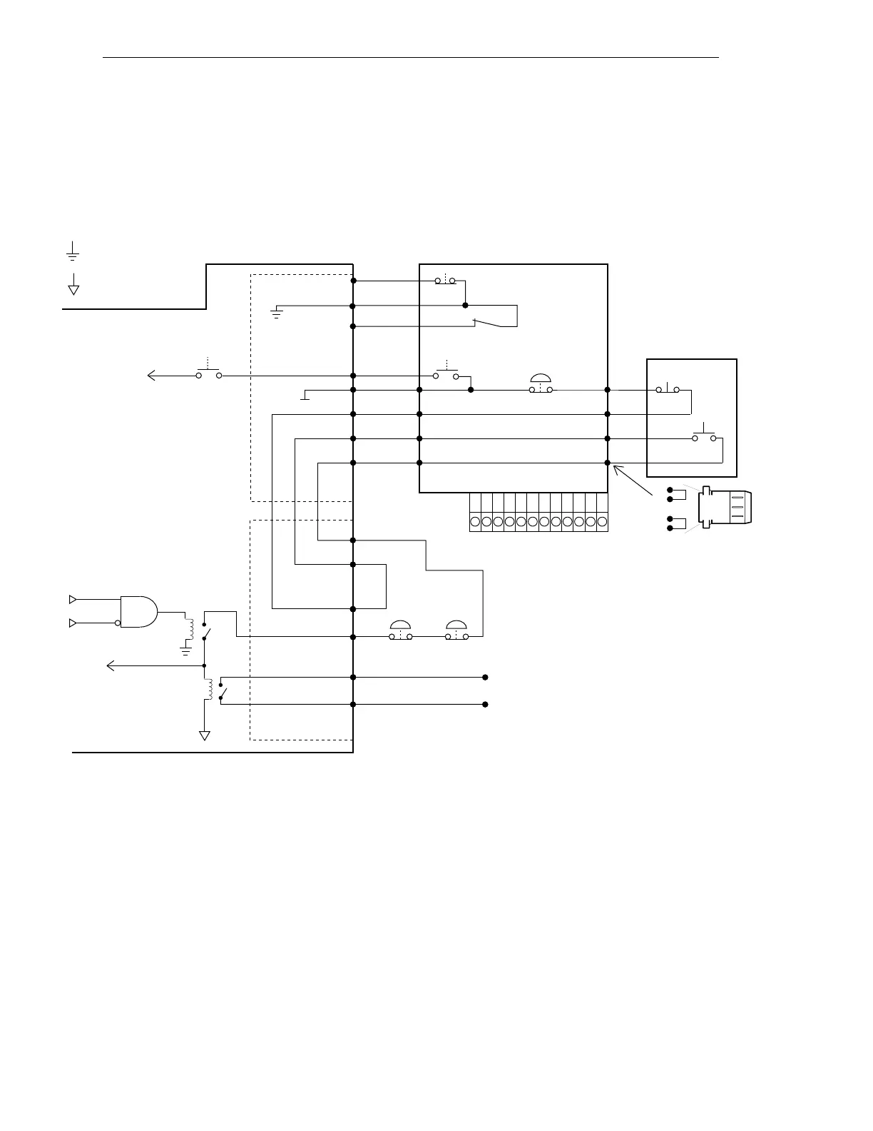
Typical Emergency Stop Circuitry
The following drawings show two examples of different types of connections to the
Emergency Stop circuitry.
Figure 3-2. E-Stop Diagram with VFP and MCP
SIO Module
Adept External Front Panel
MCP
E-Stop
Hold-to-Run
System
Power (VFP Switch)
System Power
(Controller
Switch)
E-Stop
System Power
Enable
FP/MCP Connector
22,12
9
11
19
7
6
14
16
7
6
16
14
MCP Bypass
Plug, install
if no MCP
in system
To Power Relay
= Digital Return
= Analog Return
6
7
14
16
6
7
14
16
Digital I/O
Connector
E-Stop Signal
to backplane
Passive E-Stop Output
(0.8 A at 12 VDC,
0.4 A at 24 VDC,
see text)
41
42
45
46
Enable
Power
System
Faults
User External
E-Stop Devices
External E-Stop Input
41
42
44
43
E-Stop
Voltage
To user
equipment
High Power
On/Off Push Button
Manual/Auto
Keyswitch
1211
12
3
4
5
678
910
Terminal Block
at the back of the VFP
Artisan Technology Group - Quality Instrumentation ... Guaranteed | (888) 88-SOURCE | www.artisantg.com