Installing the Signal Interface Box (SIB)
AdeptModules Instruction Handbook, Volume 1: Adept MV Controller Interface, Rev. A 47
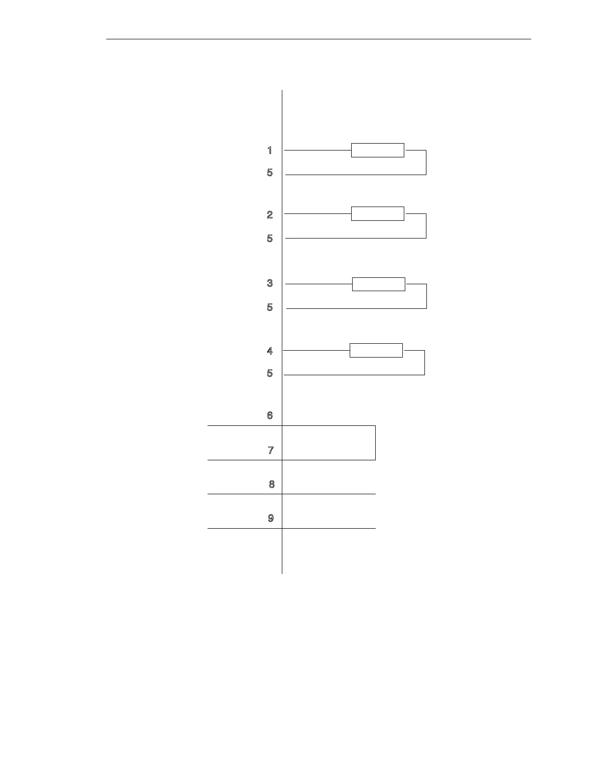
Figure 2-10. User Output Wiring Diagram
The four user outputs on the User Output/Brake Release connector are used in
conjunction with the following MV controller signals (refer to Table 2-5). Other Adept V
+
programming commands are available to control the user outputs (refer to the V+
Language User’s Guide for these commands).
+
+
+
+
-
-
-
-
1
2
3
5
5
5
5
6
7
8
9
4
Load
Load
Signal 3001
User Output #1
Signal 3001
Signal 3001
User Output #1
User Output #1
Internal use only
Manual Brake Release
User-Supplied Equipment
User Output #1
Adept-Supplied Equipment
Load
Load
Signal 3001
Artisan Technology Group - Quality Instrumentation ... Guaranteed | (888) 88-SOURCE | www.artisantg.com