Installing the Signal Interface Box (SIB)
AdeptModules Instruction Handbook, Volume 1: Adept MV Controller Interface, Rev. A 49
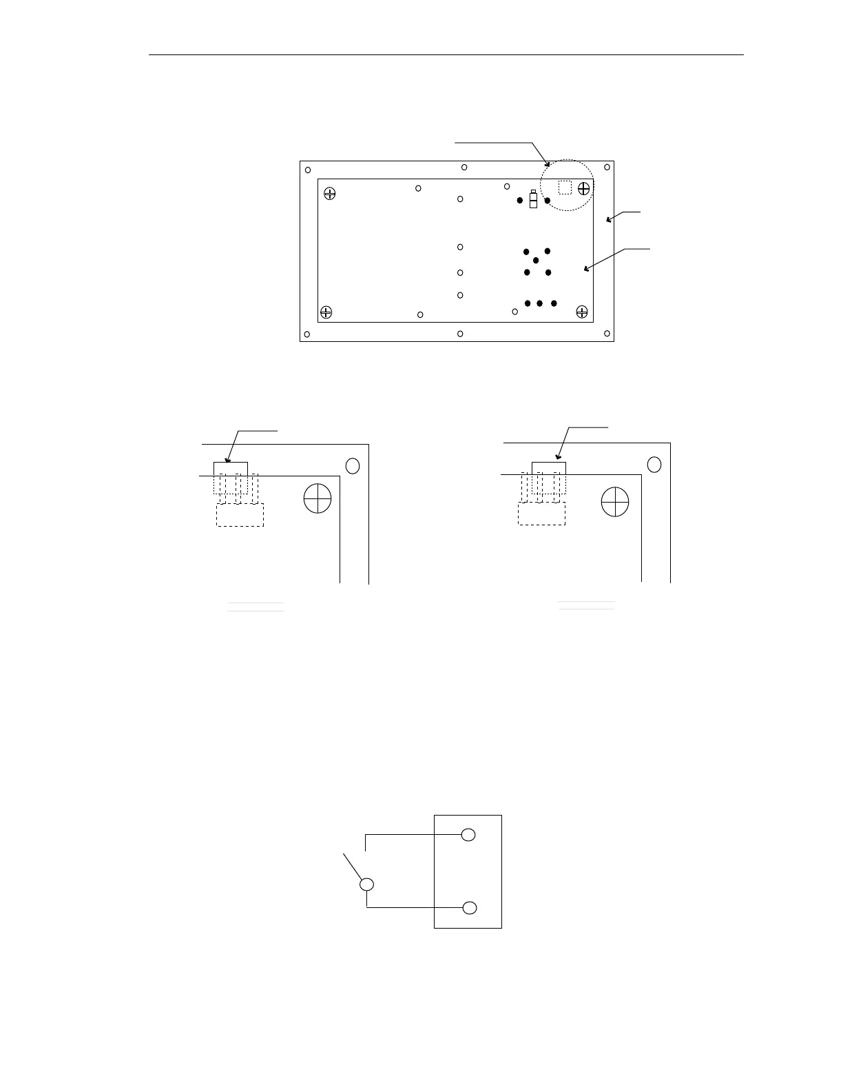
Figure 2-11. Configuring 12 or 24 Volts
Installing a Brake Release Button
When using AdeptModules with a brake mechanism, Adept recommends installation of a
brake release button so the brake can be disabled and the axis moved manually. To install
this switch, connect a momentary contact switch to pins 8 and 9 on the User Output /
Brake Release connector on the Signal Interface Box (See Figure 2-8). The switch should be
located in a position that can be reached in an emergency and should be correctly labeled.
Figure 2-12. Brake Release Button
+
+ +
JP1
Board
Front Cover
See view A and B
View of noncomponent side
24V ( DEFAULT SETTING.)
JP1
View A
View B
12V
JP1
User Output / Brake Rel connector
Pin 9
Pin 8
Artisan Technology Group - Quality Instrumentation ... Guaranteed | (888) 88-SOURCE | www.artisantg.com