Installing the External Front Panel
AdeptModules Instruction Handbook, Volume 1: Adept MV Controller Interface, Rev. A 41
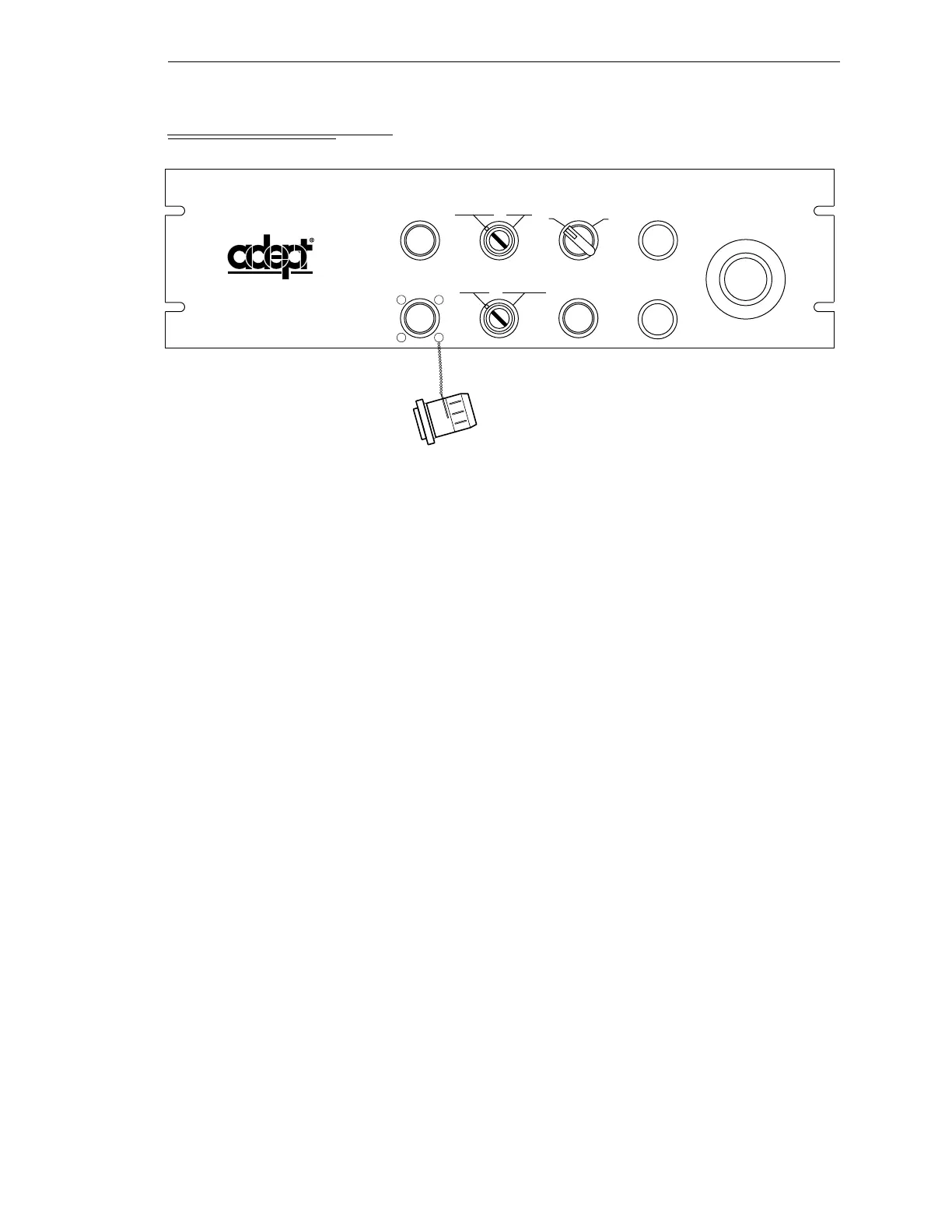
2.13 Installing the External Front Panel
Figure 2-6. External Front Panel (VFP)
Controls and Indicators
For the location of the following controls and indicators, refer to Figure 2-6.
• EMERGENCY STOP switch: This push-pull emergency stop switch removes
HIGH POWER and brings any installed motion device to an immediate stop when
pressed.
• HIGH POWER ON/OFF lamp (amber): This lamp works in conjunction with the
Enable Power command. If the amber lamp is on, the AdeptModules are operating
under servo control. When the lamp is off, the system is not under servo control.
• PROGRAM RUNNING lamp (white): When lit, this lamp indicates that a V
+
program is running. It is a warning that the AdeptModules and other mechanisms
in the workcell are under computer control and may move at any time.
• PROGRAM START switch and lamp (green): A programmer can read the status
of the button to trigger special events.
• Operating Keyswitch: The keyswitch is a two-position rotary switch marked
AUTO and MANUAL. This switch determines which operating mode is selected.
The AUTO position permits control of the system from the controller. The MANUAL
position makes the MCP the single point of control.
• Control Keyswitch: The keyswitch is a two-position rotary switch marked LOCAL
and NETWORK. This switch determines which device is able to start
AdeptModules motions. The LOCAL position makes the Manual Control Pendant
(MCP) or the connected Terminal the single point of control. The NETWORK
position is used with host supervisory control software.
• LAMP TEST switch: When the button is pressed, all the indicator lamps should
light. If an indicator does not light, check it before continuing operation.
NETWORK
HIGH POWER
ON/OFF
PROGRAM
RUNNING
SYSTEM
POWER
PROGRAM
START
LAMP
TEST
PENDANT
MANUAL AUTO
EMERGENCY STOP
I
O
®
LOCAL
Artisan Technology Group - Quality Instrumentation ... Guaranteed | (888) 88-SOURCE | www.artisantg.com