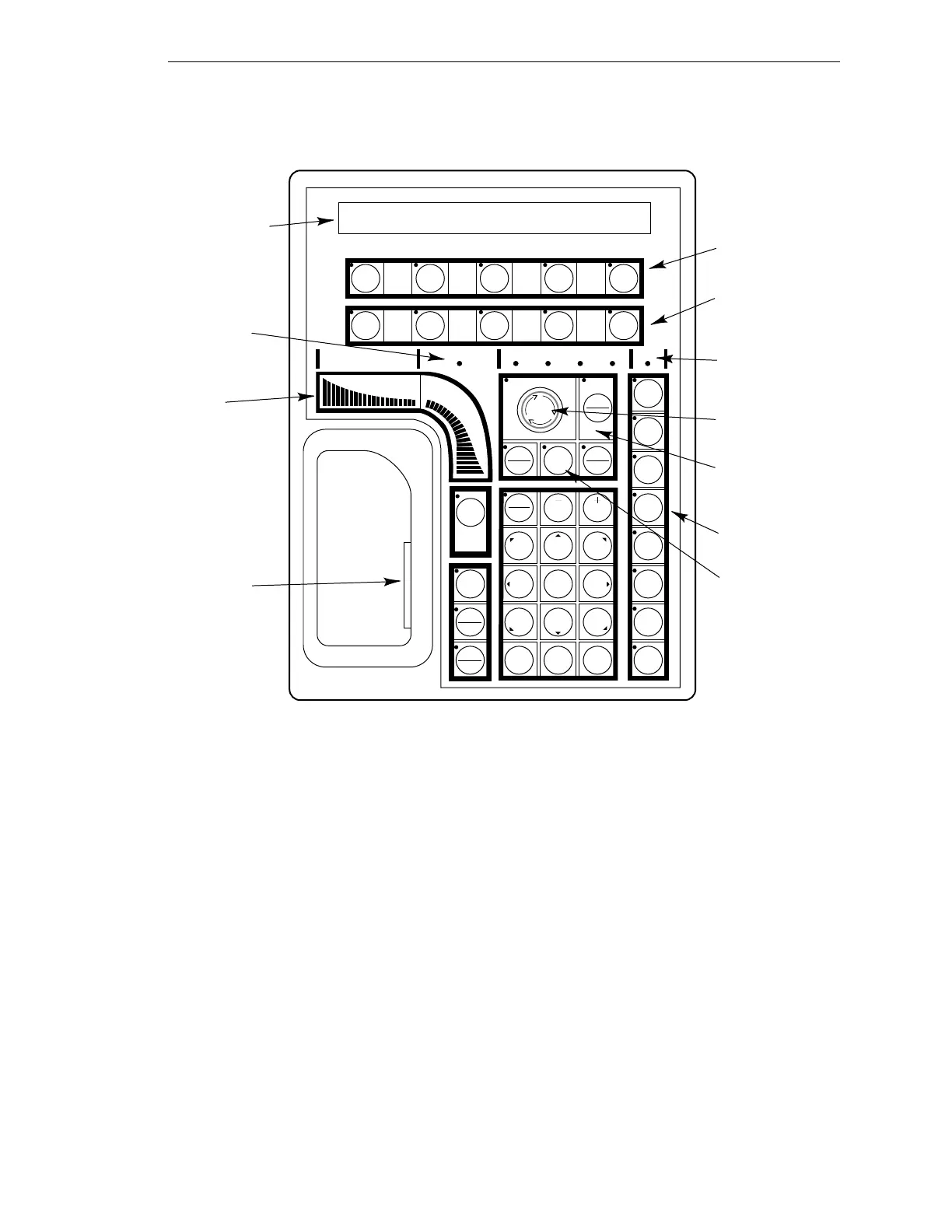
Description of the Manual Control Pendant (MCP)
AdeptModules Instruction Handbook, Volume 1: Adept MV Controller Interface, Rev. A 87
Description of Buttons on the MCP
Figure 4-2. MCP Layout
Mode Control and Joint/Axis Control Buttons
The mode control and joint/axis control buttons are used to control the AdeptModules
from the pendant.
Speed Bars
The speed bars are used to move the AdeptModules when it is in MCP Manual mode. The
slow button modifies the speed command by the speed bars.
NOTE: The Step button on the lower right corner of the MCP is used to
step through motions in a V
+
program. See the V
+
Release Notes for details.
NOTE: For more details on MCP use refer to the Adept MV Controller
User's Guide.
EDIT DISP
CLR
ERR
CMD
PROG
SET
F
F
1
2
F
3
J
7
J
12
-
SLOW
0 ¥ DEL STEP
123
456
789
T
1
RZ
6
RY
5
RX
4
Z
3
Y
2
X
1
COMP
PWR
RUN
HOLD
MAN
HALT
DIS
PWR
REC
DONE
YESNO
Liquid Crystal
Display (LCD)
User LED
Speed
Bars
Joint/Axis
Control Buttons
Disable Power
Button
Mode Control
Buttons
Manual State
LEDs
Predefined
Function
Buttons
"Soft"
Buttons
+
WORLD TOOL JOINT FREE DEV
USER
DEV
Enabling
Switch
Emergency Stop
Switch
–
Artisan Technology Group - Quality Instrumentation ... Guaranteed | (888) 88-SOURCE | www.artisantg.com