Chapter 4 - Commissioning the System
98 AdeptModules Instruction Handbook, Volume 1: Adept MV Controller Interface, Rev. A
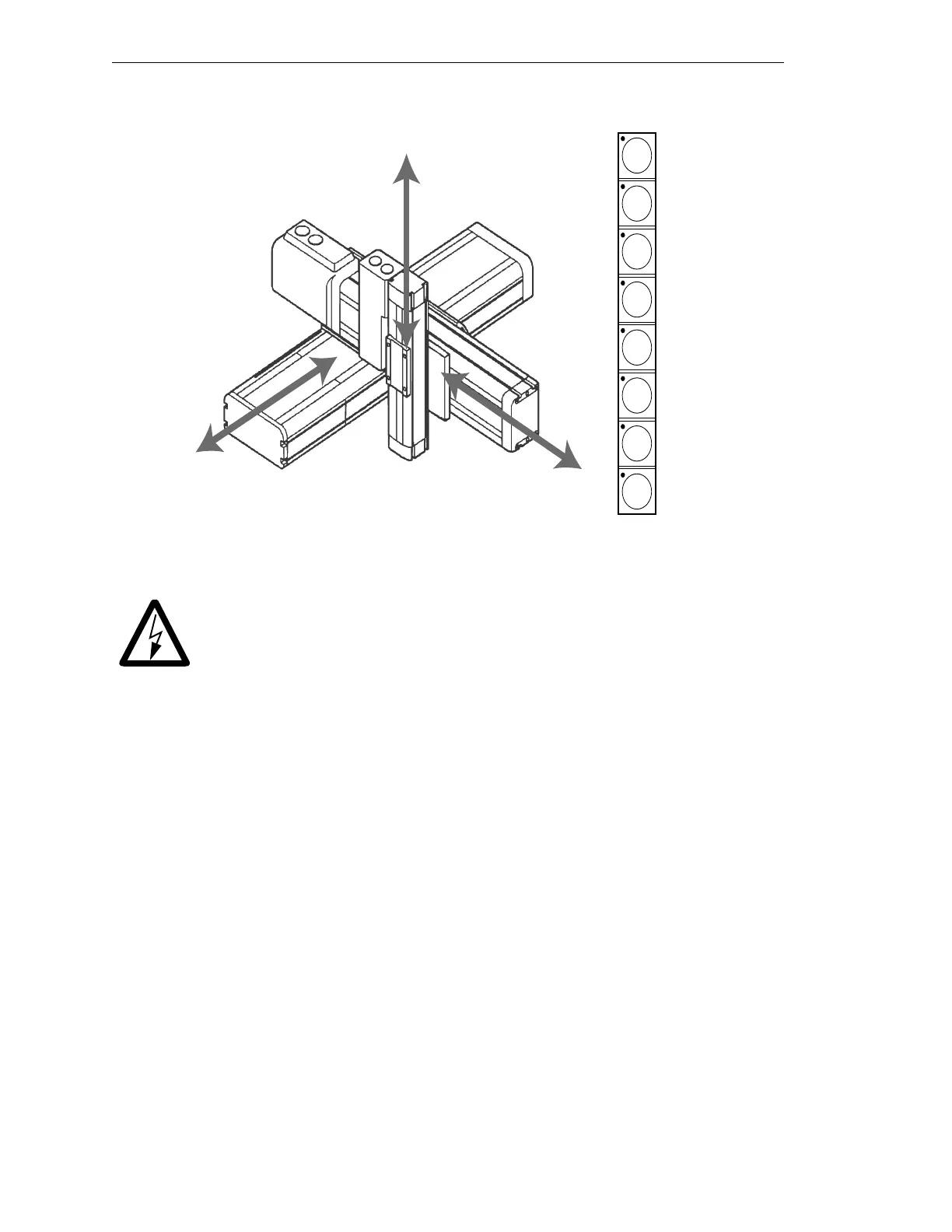
Figure 4-6. Joint State
WARNING: Before moving AdeptModules, ensure that all personnel are
out of the workcell.
In Joint State, only the selected joint moves. After calibration of the AdeptModules,
switching into Manual mode and reenabling High Power, you must select the joint mode.
1. Press the MAN/HALT button to enable the MCP.
The MCP is in the correct mode when:
a. The LED on the MAN/HALT button is illuminated. If it is not illuminated,
press the MAN/HALT button.
b. One of the manual state LEDs is also illuminated (the “Manual state” LEDs
indicate the type of manual motion that has been selected, either World, Tool,
Joint, or Free). Press the
MAN/HALT button (see Figure 4-4) several times
until the JOINT LED is illuminated.
When the LED on the MAN/HALT button and the JOINT LED are lit, Joint state is selected
and movement of a specified joint must be selected. When an Adept Z-Theta Module is
being used in Joint State, the RX/4 button on the MCP is used. In World state the Adept
Z-Theta uses RZ/6 to move.
Selecting and Moving Joint 1 (X)
Figure 4-6 shows the buttons for selecting a joint in the Joint State. Press the X1 button to
select Joint 1. The LED on the button will turn on. The user can now move that joint with
the speed bars.
T
STEP
1
RZ
6
RY
5
RX
4
Z
3
Y
2
X
1
X-Axis /Joint 1
Y-Axis /Joint 2
Z-Axis /Joint 3
JOINT 1
JOINT 2
JOINT 3
Artisan Technology Group - Quality Instrumentation ... Guaranteed | (888) 88-SOURCE | www.artisantg.com