Installing the Signal Interface Box (SIB)
AdeptModules Instruction Handbook, Volume 1: Adept MV Controller Interface, Rev. A 45
Z-THETA: This is for connecting the Adept Z-Theta module .
WARNING: Plugging into Z-Theta and the AXIS 3 and 4 connectors at the
same time will result in damage to the Signal Interface Box.
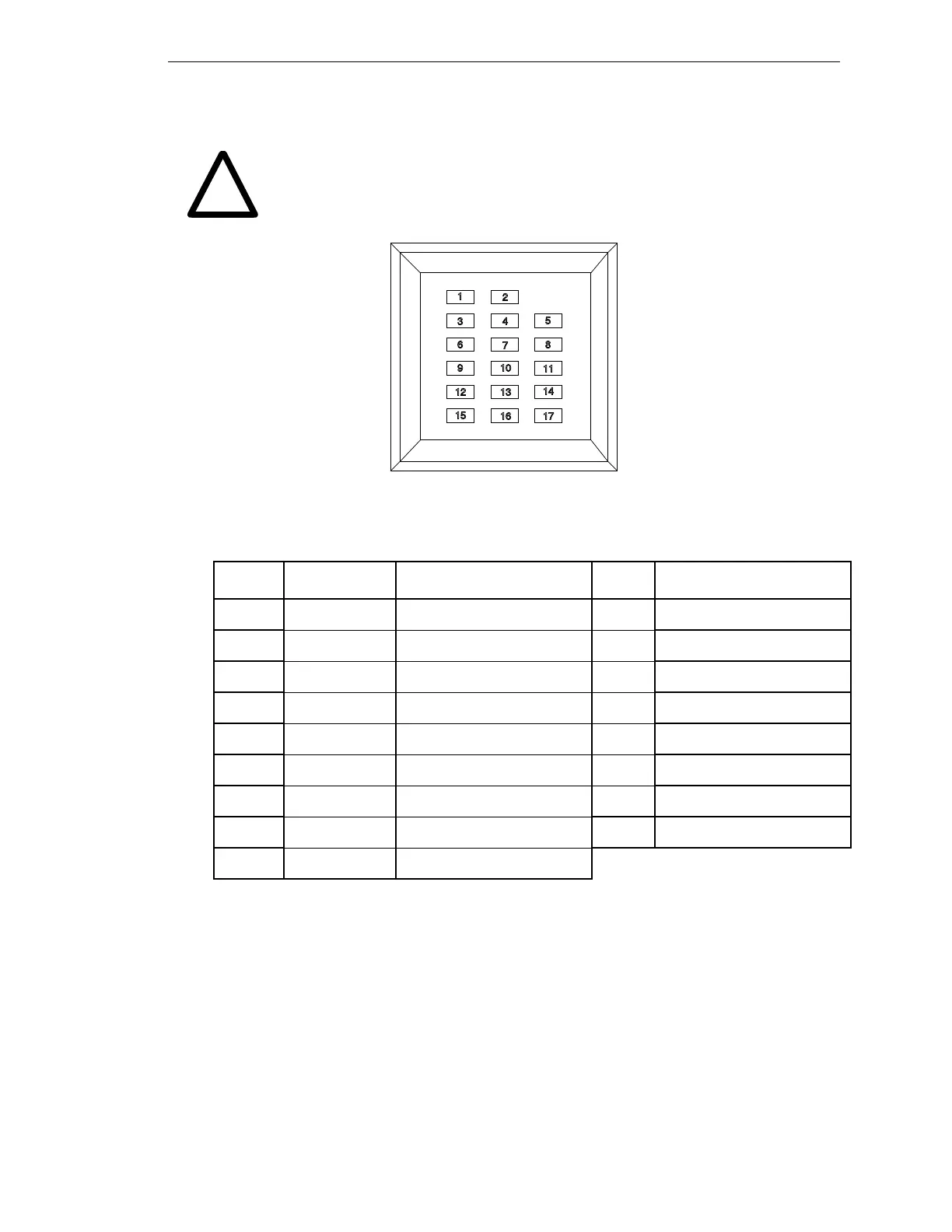
Figure 2-9. Signal Interface Box LED Indicators
Table 2-3. LED Status and Indications
LED Status Description LED Description
1 +5 Volts +5 Volts 10 Joint2 Home
2 24 Fail 24 Volt Failure 11 Joint2 Overtravel Right
3 CPU Error CPU Error 12 Joint3 Overtravel Left
4 MAN_BRK Manual Brake Release 13 Joint3 Home
5 CE_BRK Future Use 14 Joint3 Overtravel Right
6 J1_OTL Joint1 Overtravel Left 15 Joint4 Overtravel Left
7 J1_H Joint1 Home 16 Joint4 Home
8 J1_OTR Joint1 Overtravel Right 17 Joint4 Overtravel Right
9 J2_OTL Joint2 Overtravel Left
!
1
3
5
6 8
9
11
12
14
15
17
2
4
7
10
13
16
Artisan Technology Group - Quality Instrumentation ... Guaranteed | (888) 88-SOURCE | www.artisantg.com