Additional Power Chassis Information
AdeptModules Instruction Handbook, Volume 1: Adept MV Controller Interface, Rev. A 67
Power Chassis Circuit Breaker and Fuse Information
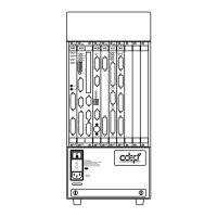
NOTE: The SSER, LVON, HPON, and ILMT labels on the lower right
corner of the front of the power chassis are for diagnostic LEDs that can
be viewed behind the front grille. These LEDs are for Adept Field Service
use only.
Chassis Circuit Breaker
The power chassis circuit breaker is rated at 15 amps and is located on the lower-left front
of the chassis on the power entry module. It also functions as an on/off switch to isolate
the chassis.
CAUTION: If the circuit breaker trips due to current overload, it indicates
an internal fault. Do not reset the circuit breaker yourself. Contact Adept
Customer Service at the numbers listed in Section 1.15.
Chassis and Amplifier Module Fuses
Six chassis fuses are located inside the base of the power chassis on the power control
board. These fuses are not user-replaceable. If you suspect that a chassis fuse may have
blown, contact Customer Service.
In addition to the fuses in the power chassis, there are additional fuses located inside the
power amplifier modules. The amplifier fuses are not user-replaceable. If you suspect that
an amplifier fuse may have blown, contact Customer Service.
CAUTION: Failure of a chassis or an amplifier fuse indicates an internal
circuit fault which must be corrected before the fuse is replaced. Do not
attempt to replace the fuse yourself. Contact Adept Customer Service at
the numbers listed in Section 1.15.
Removing and Installing Amplifier Modules
The Adept PA-4 power chassis is shipped from the factory with the amplifier modules
installed in the chassis. Any unused slots are filled with blank covers. Normally you will
not need to remove the amplifier modules. If you do need to remove and reinstall a
module for some reason, follow the instructions below. The four slots in the chassis are not
interchangeable: Some slots have special control signals. The amplifier modules are
factory-installed in the correct slots. Contact Adept Customer Service if you need to
relocate any modules.
WARNING: Do not attempt to install or remove any amplifier modules
without first turning off the power to the power chassis and all related
external power supplies. Failure to observe this warning could cause
injury or damage to your equipment.
Removing Amplifier Modules
1. Turn off the power chassis and the Adept MV controller.
2. Note the location of any cables connected to the module, then disconnect them.
3. Loosen the captive screws at the top and bottom of the module.
!
!
Artisan Technology Group - Quality Instrumentation ... Guaranteed | (888) 88-SOURCE | www.artisantg.com

 Loading...