Connecting to AC Power
AdeptModules Instruction Handbook, Volume 1: Adept MV Controller Interface, Rev. A 65
Table 2-12. Signal Interface Box AC Power Requirements
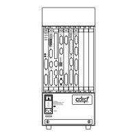
Power Entry Module
The power entry module is located on the right side of the Signal Interface Box. It
contains:
• the On/Off power switch ( I = On, o = Off)
• the AC power cord socket
• the two incoming AC line fuses, rated at 2.5 amps
• two spare 2.5 amp AC fuses, stored in fuse cover sockets
The AC power cord for the Signal Interface Box has the same specifications as the Adept
MV controller power cord. Refer to Table 2-9.
Voltage
Ranges
Minimum
Operating
Voltage
Maximum
Operating
Voltage
Current Frequency /
Phasing
100V to 120V
and
200V to 240V
90V
180V
132V
264V
2 Amps
1 Amps
50 - 60Hz,
1-Phase
Artisan Technology Group - Quality Instrumentation ... Guaranteed | (888) 88-SOURCE | www.artisantg.com

 Loading...