Moving the AdeptModules With the MCP
AdeptModules Instruction Handbook, Volume 1: Adept MV Controller Interface, Rev. A 97
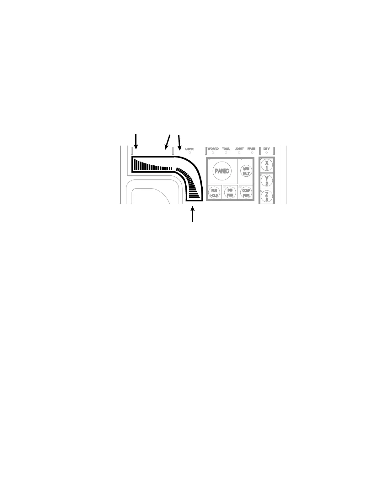
Speed Bars
The speed bars control the AdeptModules speed and direction (see Figure 4-5). The
joint(s) that will move when the speed bars are pressed depend(s) on the “state” selected
with the MAN/HALT button. Press the speed bars with your left thumb. Pressing the
speed bars near the outer ends will move the AdeptModules faster; pressing the speed bar
near the center will move the AdeptModules slower. The maximum speed of the
AdeptModules in Manual mode is 250 mm per second (10 ips).
NOTE: Refer to Appendix D for testing and troubleshooting information.
Figure 4-5. Speed Bars
Selecting Joint State and Moving the AdeptModules
Figure 4-6 shows a typical AdeptModules configuration with three degrees of movement.
Positive motion of the X-axis is away from the motor as viewed from above. Positive
movement of Z-axis is downward. Before the speed bars will move an axis, the correct
axis must be selected from the Joint /Axis control buttons.
Fast
Fast
Slow
- +
Artisan Technology Group - Quality Instrumentation ... Guaranteed | (888) 88-SOURCE | www.artisantg.com