EasyManua.ls Logo

Agilent Technologies 4288A User Manual

Agilent Technologies 4288A
289 pages
To Next Page IconTo Next Page
To Previous Page IconTo Previous Page
Page #252 background imageLoading...
Page #252 background image
250 Appendix C
Status Reporting System
General Status Register Model
Condition register and transition filter
When the status register has a transition filter, there is a lower register called a condition
register under the event register. The transition filter is between the event register and the
condition register.
The transition filter enables you to select a positive and/or negative transition of the
condition register bit in order to set a bit in the corresponding event register. For example,
using the negative transition filter to set bit 3 to “1” causes bit 3 of the event register to be
set to “1” when bit 3 of the condition register makes a negative transition, that is, changes
from 1 to 0.
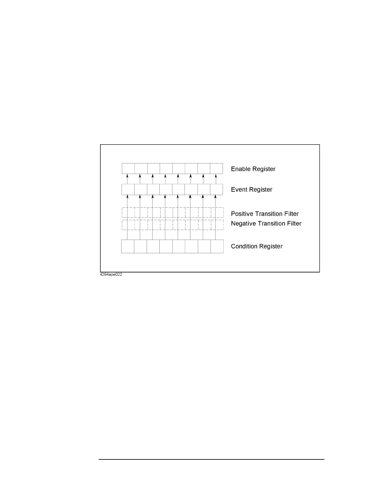
Figure C-2 Transition filter and condition register
The 4288A's condition register and transition filter work only with the operation status
register. However, the 4288A's transition filters setting is fixed so that bits 5, 8, 9, 10 of
the event register are set to “1” when the condition register makes a positive transition (i.e.,
changes from 0 to 1) and bits 1, 2, 3, 4, 7, 12 of the event register are set to “1” when the
condition register makes a negative transition (i.e., changes from 1 to 0).

Table of Contents

Question and Answer IconNeed help?

Do you have a question about the Agilent Technologies 4288A and is the answer not in the manual?

Agilent Technologies 4288A Specifications

General IconGeneral
Frequency Range20 Hz to 1 MHz
Basic Accuracy0.1%
DisplayLCD
Frequency20 Hz to 1 MHz
Maximum AC signal level2 Vrms
InterfaceGPIB, RS-232
Measurement ParametersC, L, R, D, Q
Input Impedance1 MΩ
Power Requirements100 V to 240 V, 50 Hz to 60 Hz
Measurement TypeCapacitance (C), Inductance (L), Resistance (R), Dissipation Factor (D), Quality Factor (Q)
Bias Current0 to +100 mA (programmable)

Summary

2 Overview of Remote Control

Setting Up a GPIB Remote Control System

Explains how to set up a GPIB remote control system for the Agilent 4288A.

3 Setting Up Measurement Conditions and Display

Setting Up Measurement Conditions

Details how to configure measurement parameters like frequency, range, time, averaging, and trigger delay.

4 Preparation for Accurate Measurement (Executing Compensation)

Executing OPEN/SHORT/LOAD Compensation

Details the process of performing OPEN, SHORT, and LOAD compensation for accurate measurements.

Using the Multi-compensation Function

Enables and configures multi-compensation for multiple channels or parameters.

5 Starting (Triggering) Measurement and Waiting for Completion of Measurement

Starting (triggering) Measurement

Describes the trigger system states and methods for starting measurements automatically or on demand.

Waiting For Completion Of Measurement (detecting completion of measurement)

Explains detecting measurement completion using SRQ and status registers for program flow.

6 Reading Out Measured Result

Reading out measured result using *TRG command

Describes using *TRG to trigger measurement and immediately read results.

Reading out measured result using :FETC? command

Explains using :FETC? for triggering and reading results, suitable for external controllers.

7 Sorting Based on Measured Result (Comparator Function)

Setting Up Comparator Function

Explains enabling the comparator and configuring limit ranges for sorting measurements.

8 Avoiding Mistakes Related to Work and Daily Checks

Detecting the occurrence of an error

Explains methods for detecting errors using the error queue and status report system.

9 Measurement Applications (Sample Programs)

B Information for Replacing 4278A with 4288A

Compensation

Compares compensation functions (ON/OFF, parameter format, standard setup, alarm messages).

Comparator

Compares sorting parameters, limit modes, BIN sorting, AUX BIN, and Low C reject functions.

C Status Reporting System

D Initial Settings

Initial Settings, Settings that can be Saved/Recalled, Settings that can be Backed Up

Provides initial, save/recall, and backup settings for instrument configuration.

E At-a-glance Table of Operations When Overload or Low C is Detected

Operations when overload/Low C is detected

Describes display, GPIB, and handler interface outputs for overload or Low C conditions.

F Error Messages

Error Messages

Lists error messages and their remedies, ordered by error number.

G 4268A vs. 4288A GPIB Command Correspondence Table

Related product manuals