EasyManua.ls Logo

Agilent Technologies 4288A User Manual

Agilent Technologies 4288A
289 pages
To Next Page IconTo Next Page
To Previous Page IconTo Previous Page
Page #62 background imageLoading...
Page #62 background image
60 Chapter 6
Reading Out Measured Result
Data Transfer Format
Binary transfer format
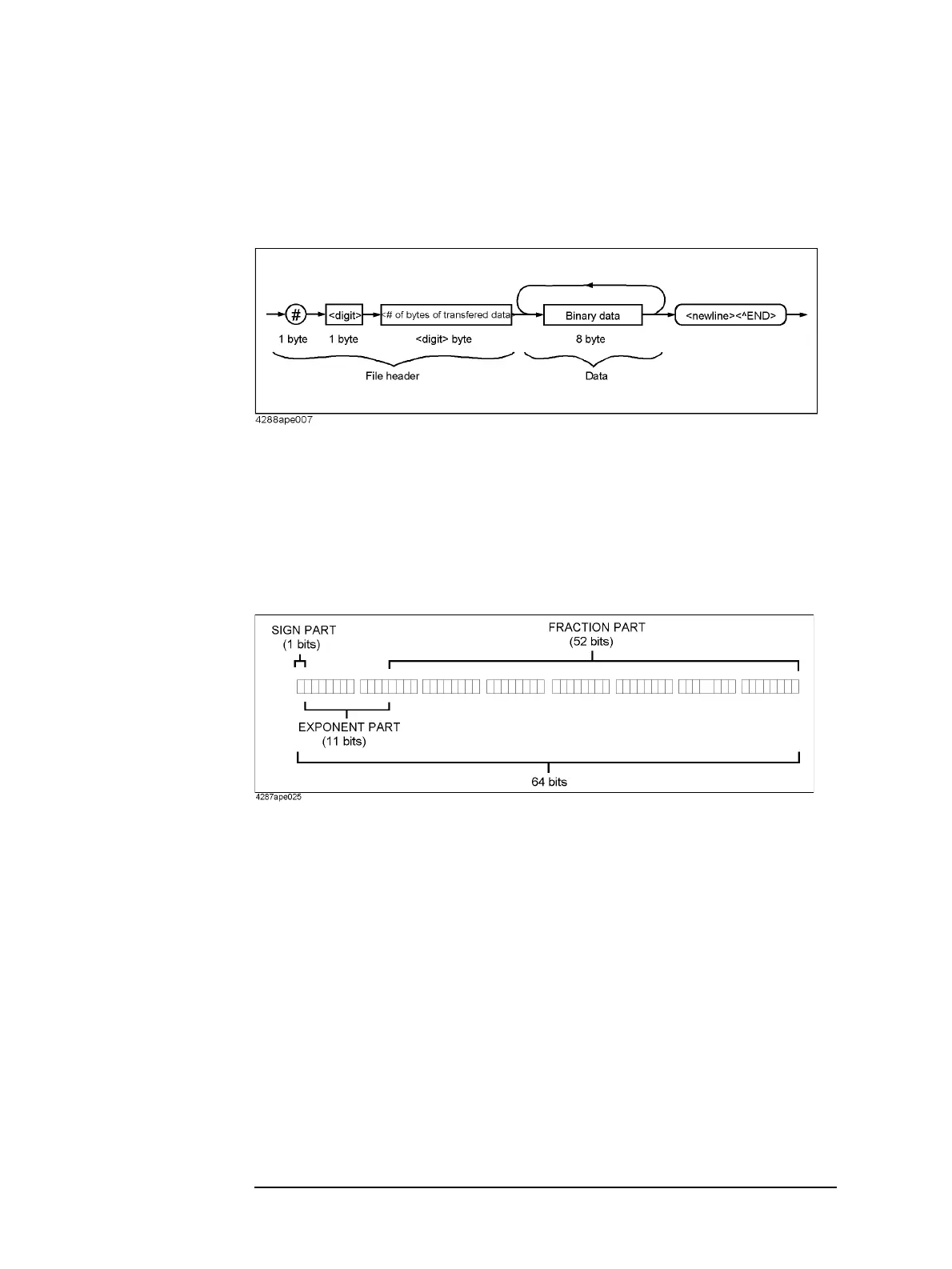
When data is transferred in the binary transfer format, values (binary data) are transferred
in the format shown in Figure 6-3.
Figure 6-3 Binary transfer format
In this data transfer format, a pounds symbol (#) occurs at the beginning. The 2nd byte
<digit count> indicates the number of bytes in the <transfer data byte count> part. The
<transfer data byte count> indicates the total number of bytes of the binary data. <new
line><^END> is the message terminator.
Binary data is in the IEEE 754 floating point format consisting of 64 bits as shown in
Figure 6-4.
Figure 6-4 64-bit floating-point data
Byte order
In binary transfer, data bytes (8 bytes) are transferred from the byte including the MSB
(Most Significant Bit) (the left-most byte in Figure 6-4) through the byte including the LSB
(Least Significant Bit) (the right-most byte in Figure 6-4).

Table of Contents

Question and Answer IconNeed help?

Do you have a question about the Agilent Technologies 4288A and is the answer not in the manual?

Agilent Technologies 4288A Specifications

General IconGeneral
Frequency Range20 Hz to 1 MHz
Basic Accuracy0.1%
DisplayLCD
Frequency20 Hz to 1 MHz
Maximum AC signal level2 Vrms
InterfaceGPIB, RS-232
Measurement ParametersC, L, R, D, Q
Input Impedance1 MΩ
Power Requirements100 V to 240 V, 50 Hz to 60 Hz
Measurement TypeCapacitance (C), Inductance (L), Resistance (R), Dissipation Factor (D), Quality Factor (Q)
Bias Current0 to +100 mA (programmable)

Summary

2 Overview of Remote Control

Setting Up a GPIB Remote Control System

Explains how to set up a GPIB remote control system for the Agilent 4288A.

3 Setting Up Measurement Conditions and Display

Setting Up Measurement Conditions

Details how to configure measurement parameters like frequency, range, time, averaging, and trigger delay.

4 Preparation for Accurate Measurement (Executing Compensation)

Executing OPEN/SHORT/LOAD Compensation

Details the process of performing OPEN, SHORT, and LOAD compensation for accurate measurements.

Using the Multi-compensation Function

Enables and configures multi-compensation for multiple channels or parameters.

5 Starting (Triggering) Measurement and Waiting for Completion of Measurement

Starting (triggering) Measurement

Describes the trigger system states and methods for starting measurements automatically or on demand.

Waiting For Completion Of Measurement (detecting completion of measurement)

Explains detecting measurement completion using SRQ and status registers for program flow.

6 Reading Out Measured Result

Reading out measured result using *TRG command

Describes using *TRG to trigger measurement and immediately read results.

Reading out measured result using :FETC? command

Explains using :FETC? for triggering and reading results, suitable for external controllers.

7 Sorting Based on Measured Result (Comparator Function)

Setting Up Comparator Function

Explains enabling the comparator and configuring limit ranges for sorting measurements.

8 Avoiding Mistakes Related to Work and Daily Checks

Detecting the occurrence of an error

Explains methods for detecting errors using the error queue and status report system.

9 Measurement Applications (Sample Programs)

B Information for Replacing 4278A with 4288A

Compensation

Compares compensation functions (ON/OFF, parameter format, standard setup, alarm messages).

Comparator

Compares sorting parameters, limit modes, BIN sorting, AUX BIN, and Low C reject functions.

C Status Reporting System

D Initial Settings

Initial Settings, Settings that can be Saved/Recalled, Settings that can be Backed Up

Provides initial, save/recall, and backup settings for instrument configuration.

E At-a-glance Table of Operations When Overload or Low C is Detected

Operations when overload/Low C is detected

Describes display, GPIB, and handler interface outputs for overload or Low C conditions.

F Error Messages

Error Messages

Lists error messages and their remedies, ordered by error number.

G 4268A vs. 4288A GPIB Command Correspondence Table

Related product manuals