52 Chapter 5
Starting (Triggering) Measurement and Waiting for Completion of Measurement
Starting (triggering) Measurement
Starting (triggering) Measurement
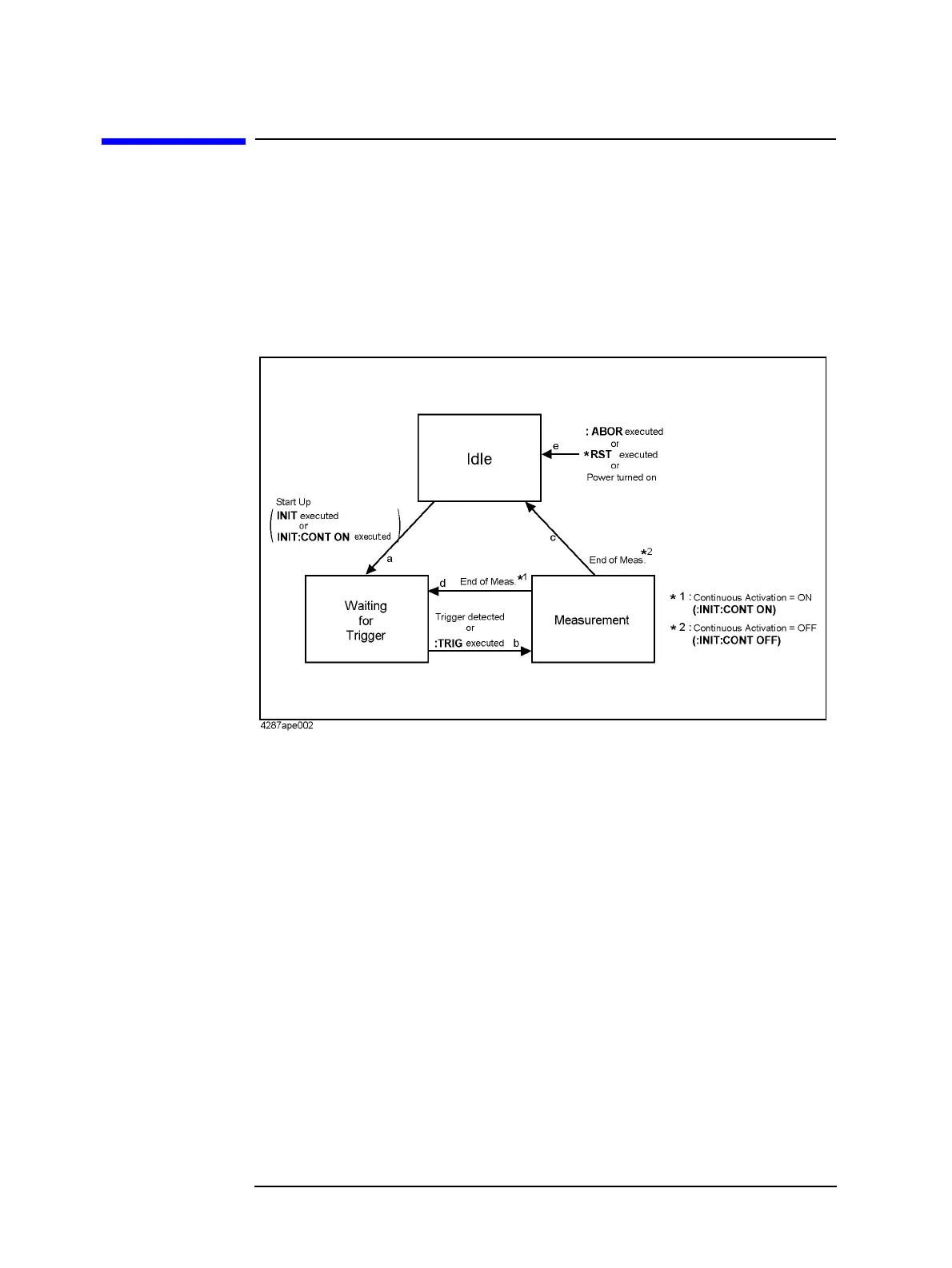
Trigger system
The operations performed by the trigger system include detection of the measurement start
signal (trigger) and control of the delay time for starting measurement. The trigger system
has three states: “idle,” “waiting for trigger,” and “measurement,” as shown in Figure 5-1.
Figure 5-1 Trigger system
Each state of the trigger system and the transitions between them are described below.
Idle state
When the following commands are executed, the trigger system transitions to the idle state
(e in Figure 5-1). The idle state is also in effect immediately after power-on. Because the
continuous activation of the trigger system and the trigger mode are set to ON and internal
trigger, respectively, at power-on, the trigger system immediately transitions to the waiting
for trigger state and then repeats the transition between the measurement state and the
waiting for trigger state.
• *RST on page 126
• :ABOR on page 130
When the trigger system is started up using the following commands, it transitions to the
waiting for trigger state (a in Figure 5-1).
• :INIT on page 183
• :INIT:CONT on page 183 (when executed with ON specified)