Lesson 3 – Synchronization of Analog Modules
146
3-1 Synchronization + Triggering
An analog module starts the operation when it receives a trigger
signal. Normally the trigger signal for the analog module is
provided by a digital channel. To send the trigger signal, you must
connect the digital pin that provides the trigger signal and the
trigger input pin of the analog module via a DUT board
connection.
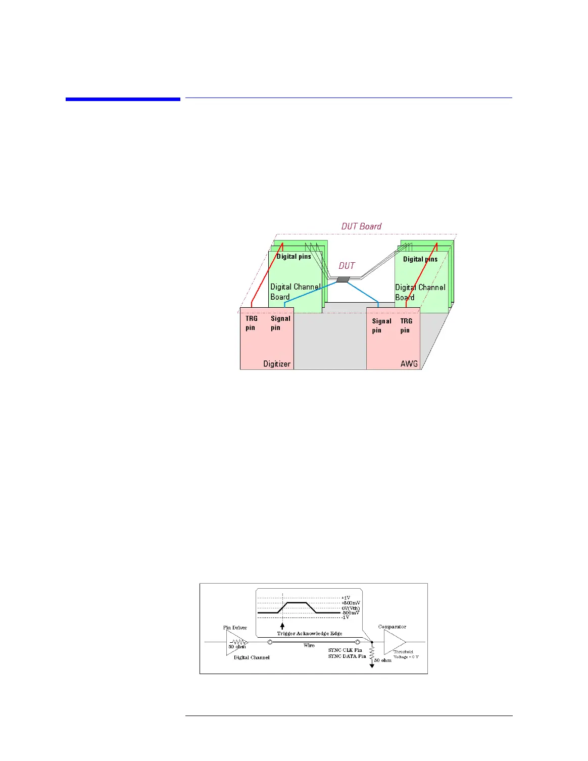
Trigger Signals for Analog Modules
To provide a path for sending a trigger signal, connect the trigger
input pin (SYNC CLK) to a digital channel that sends a trigger
signal on the DUT board.
The pulse width of the trigger signal must be greater than or equal
to 8 ns. If the pulse width of the trigger signal is smaller than 8 ns,
the trigger signal may be missed by the analog module.
The input impedance of the SYNC CLK pin is 50 ohm. The
threshold level of the comparator of the SYNC CLK pin is fixed to
0.0 V. The analog module activates by the rising edge of the trigger
signal, that is, 0.0 V point of the rising edge. The recommended
level of the trigger signal is ±500 mV (@50 ohm termination). To
set as this, specify the level of the trigger signal to ±1 V in the
level setup window. The level of the trigger signal must be within
±1 V (@50 ohm termination).
Synchronization Trigger

 Loading...


