Lesson 1 – Analog Clock Domain Description
370
1-3 Clock Distribution between Card
Cages
This section summarizes the clock distribution between the card
cages of the testhead for the digital and for the analog clock
domain. In the previous section, the clock distribution to the slots
in an analog card cage was shown.
The clock boards of the card cages are the central points for the
clock distribution. They can generate clock signals, and distribute
these signals, or the clock signals from an AMC, to the slots and to
the clock boards of their neighbor cages.
The following diagrams show the clock distribution for the
available testhead configurations.
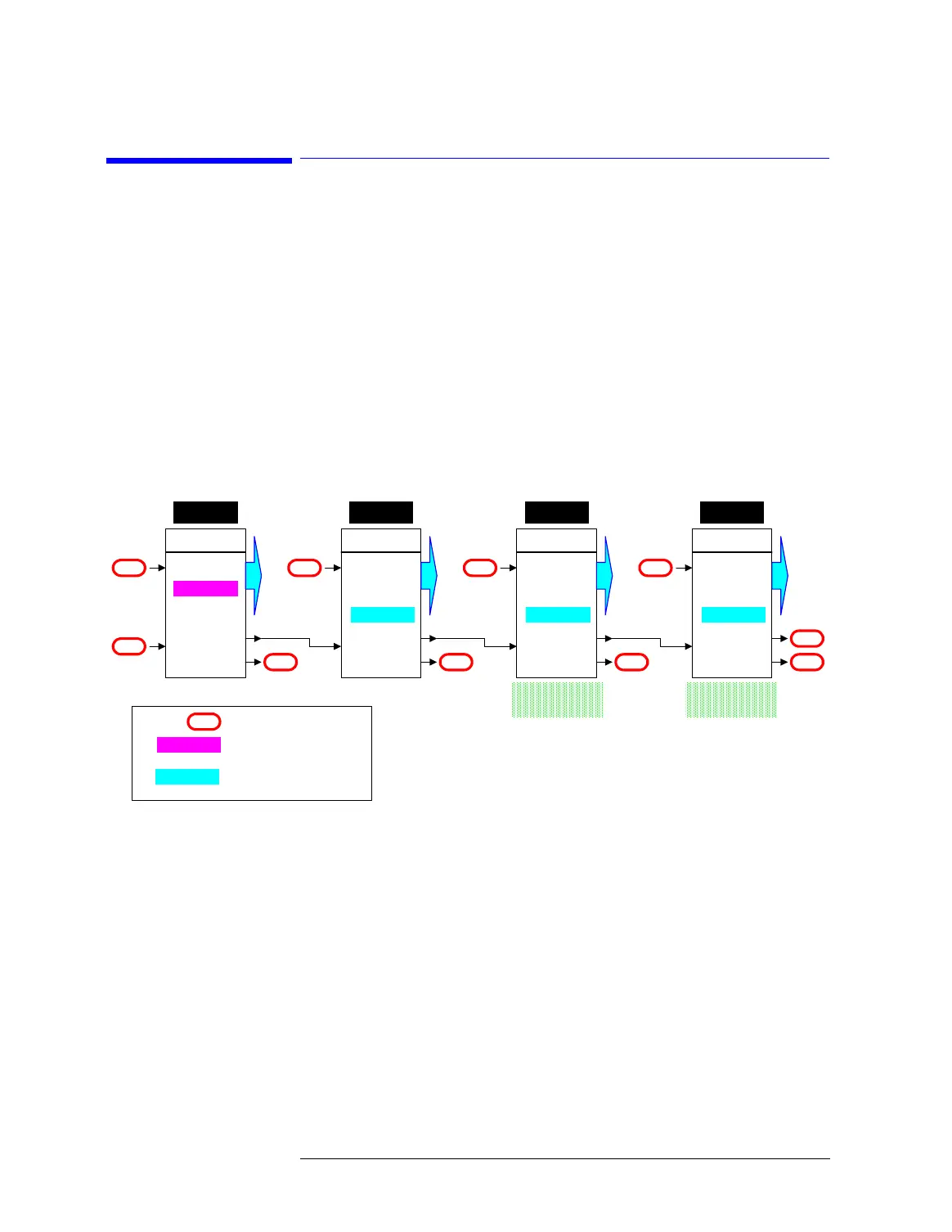
Clock Distribution 512 Testhead (no AMC, Digital Domain only)
In the figure above, the clock board in card cage 1 generates the
clock signal (master). The signal is distributed via Ring A to all
other clock boards (slaves).
Note: Although named Ring, the signal line A is not a closed loop.
Master
Local PLL
RING A
RING B
Ring
Ext.
C. Cage 1
NC
NC
SLOTS
Slave
RING A
RING B
Ring
Ext.
C. Cage 4
NC
NC
SLOTS
Slave
RING A
RING B
Ring
Ext.
C. Cage 2
NC
NC
SLOTS
Slave
RING A
RING B
Ring
Ext.
C. Cage 3
NC
NC
SLOTS
NC
Ring Ring Ring
Analog Card Cage Analog Card Cage
NC
NC
Not Connected
Local PLL
Ring
Clock generated by PLL
Clock forwarded from the
previous clock board

 Loading...


