Lesson 2 – DUT Board Design Considerations
529
2-1 DUT Board Overview
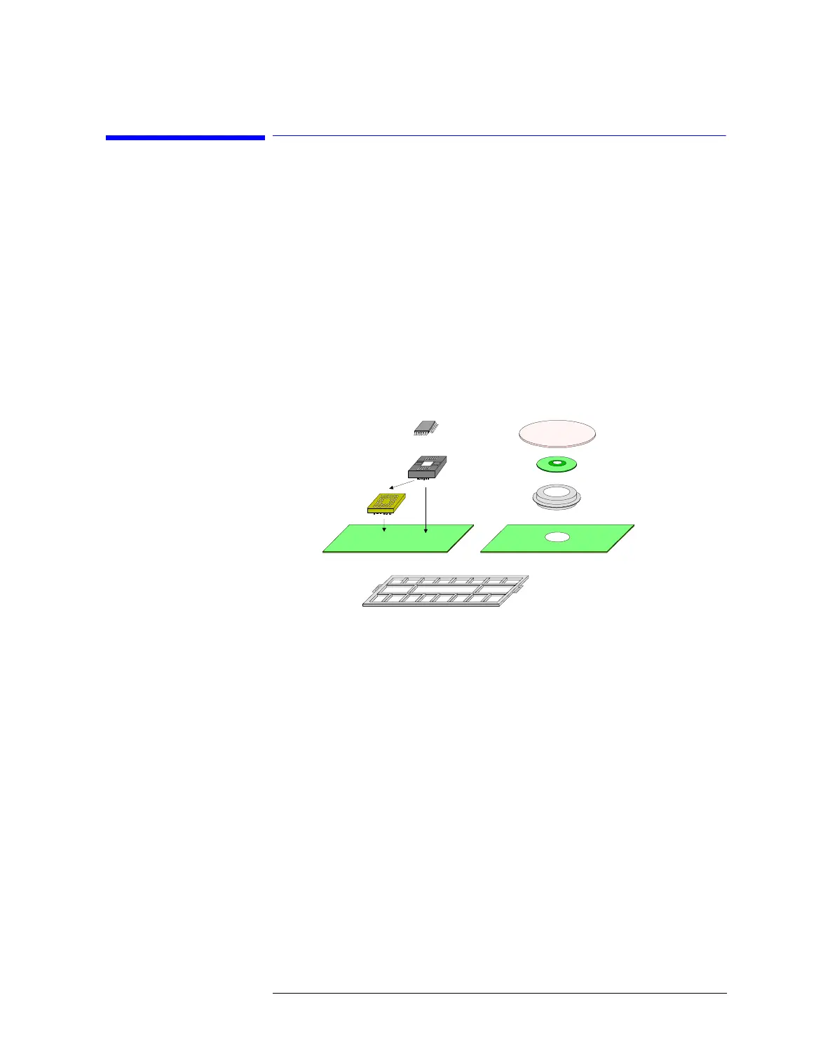
If a packaged device is tested, an IC socket is mounted on the DUT board
to connect the device to the test system hardware.
The IC socket can be directly mounted on the DUT board. For pro-
duction tests, the socket adapter is generally used between the IC
socket and DUT board so that the IC socket can be replaced easily if
it breaks.
If a wafer device is tested, a probe card, pogo tower, and Wafer
Prober Interface (WPI) DUT board are used to connect the wafer
device to the test system hardware.
DUT Board and WPI DUT Board Items
Whatever solution you choose, in most cases additional components will
have to be mounted on the DUT board or WPI DUT board, such as:
• Resistors
• Capacitors
• Relays
• OpAmps
• Filters
• Digital ICs
Because the general considerations are essentially the same, the following
explanations do not differentiate between DUT board and WPI DUT board.
DUT boards interact with the test system through blocks of pogo pins.
Each pogo block communicates with the test system hardware, meaning the
Packaged Device
DUT
Board
WPI DUT
Board
DUT Board
Stiffener
Pogo Tower
Wafer Device
Probe Card
IC Socket
Socket
Adapter

 Loading...


