Lesson 4 – Defining the Signal Routing
211
4-1 Analog Routing Basics
All analog modules have a relay multiplexer which allows you to
set the signal routes between input/output pins of the module and
the module itself.
This lets you select the input pin(s) to provide the input signal to a
measurement module (digitizer, sampler, or TIA), or the output
pin(s) to carry the output signal from a signal generating module
(AWG).
The input and output pins of each analog module, and the
switches of the relay multiplexer are shown in “Analog Modules”
on page 59.
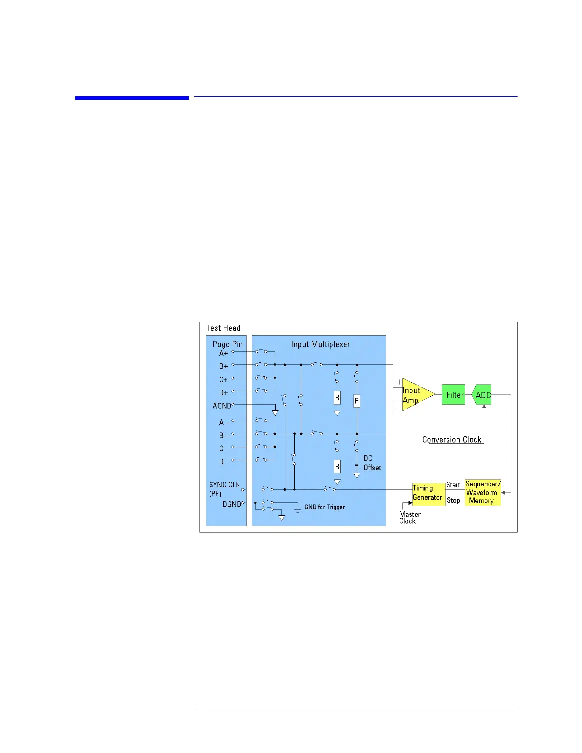
The following figure shows the input pins and the multiplexer of
the High Speed Digitizer (WDA).
Block Diagram of High Speed Digitizer (WDA)
In addition to the signal routes to and from an analog module, also
routes from one input or output pin to another one, and to the
trigger pin (SYNC CLK) of the analog module can be made.A route
to the trigger pin is used to perform DC measurements at a DUT
pin, using the measurement capabilities of the digital pin
connected to the trigger.

 Loading...


