Lesson 2 – TIA Setup
493
2-4 Defining the Routing
The routing for a TIA test is defined with the Routing Setup Tool.
The routing defines how the input pins to the front-end module get
connected to the possible two TIAs that are connected to the front-
end module.
Each front-end input pin can be connected to each TIA as either
channel 1 or channel 2.
The terminology used in the Routing Setup Tool differs from that
used in the Analog Setup Tool.
The input channels 1 and 2 to a TIA instrument (core) are called
IO #1 and IO #2. The two TIA instruments are referred to as Core
#1 and Core #2.
The operation of the Routing Setup Tool has been described in
“Defining the Signal Routing” on page 209.
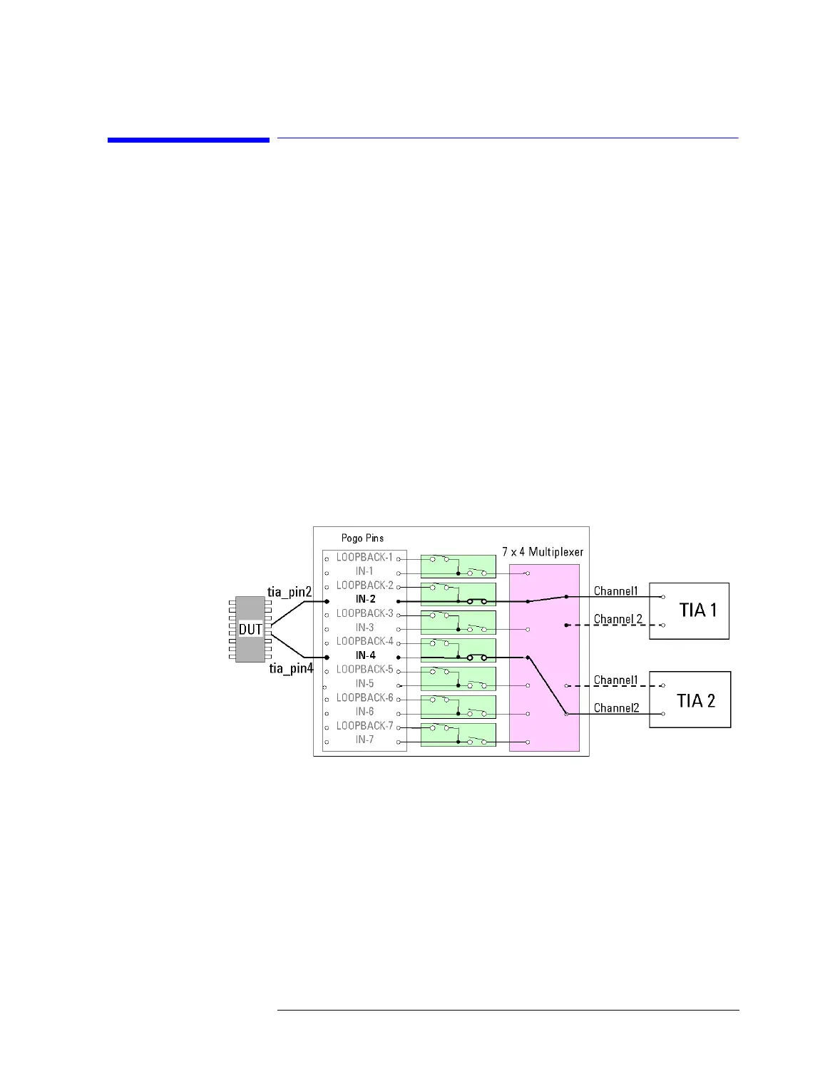
The following figure shows an example routing with pin
connections to any TIA and any TIA input channel.
TIA Routing Example
The next figure shows how to implement this routing with the
Routing Setup Tool.

 Loading...


