Lesson 2 – Addressing the Analog Modules
139
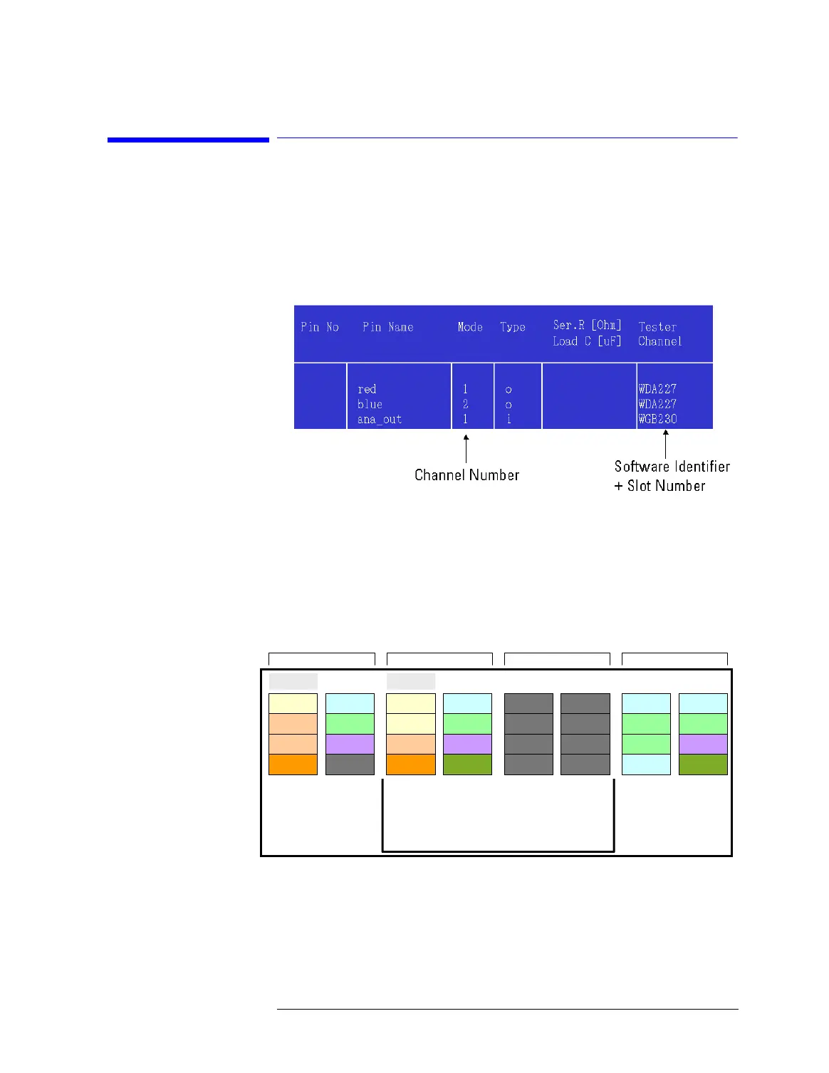
2-3 Identification of Analog Channels
in the Software
In the Pin Configuration Editor, a pin of an analog module is
specified by the software identifier of the module + slot number
and channel number:
The analog module’s channel number is entered in the Mode
column of the pin configuration editor, the software identifier and
slot number in the Tester Channel column.
As described before, the slots to be occupied by analog modules
are in the card cages corresponding to groups 6, 7, and 8.
The following figure shows possible analog module locations:
Analog module locations
On the DUT board, one analog module corresponds to one pogo
pin block. To specify pin(s) for the desired analog module, a
channel number is required which refers to the respective input or
output pin of the module.
Group 8 Group 6Group 7 Group 2
1
2
3
4
1
2
3
4
1
2
3
4
1
2
3
4
5
6
7
8
5
6
7
8
5
6
7
8
5
6
7
8
224
WGA/E -3
222
WGB/D -2
220
WDB/E -5
219
WDA/D/G -5
218
SPA/B(5,6)
217
Blank
232
WGA/E -1
230
WGB/D -1
228
WDB/E -1
227
WDA/D/G -1
226
SPA/B(1,2)
229
WGC/F -1/3
225
TIA -1A/B
116
111
112
114 110
113 109
216
WDB/E -3
212
WDB/E -2
211
WDA/D/G -2
210
SPA/B(3,4)
213
WDB/E -4
209
TIA -2A/B
SOURCE SOURCE MEAS MEASMEASMEAS Digital Digital
221
WGC/F -2/4
231
WGA/E -2
223
WGB/D -3
215
WDA/D/G -3
115
214
WDA/D/G -4
Small Testhead
Large Testhead
Cage6 Cage8Cage4 (small TH)
Cage2 (large TH)
Cage2 (small TH)
Cage4 (large TH)
MCA Source&Measure module: 231=>232=>224
MCA Measure module: Same as for WDB

 Loading...


