Lesson 2 – Addressing the Analog Modules
138
Multi-site Baseband Analog Source&Measure /
Multi-site Baseband Analog Measure
The Multi-site Baseband Analog (MCA) modules contain eight
units. For the E9714A MCA Source&Measure module, units 1 to 4
are the source units and units 5 to 8 are the measure units. For
the E9715A MCA Measure module, all units are the measure units.
Each source unit contains an audio AWG (1.024 Msps 24-bit), a
video AWG (100 Msps 14-bit), and so on. Each measure unit
contains one video digitizer (65 Msps 14-bit), two audio digitizers
(200 ksps 24-bit), and so on.
Each unit have two sorts of the trigger input pins: the common
trigger pins (CT1 and CT2) and unit trigger pins (AA+, BB+, CC+,
..., and HH+). The common trigger pins can be shared with any
units in an MCA. Each trigger input pin has the same function as
the SYNC CLK pin in other analog modules. For details of
available function in each pin, see the System Reference manual.
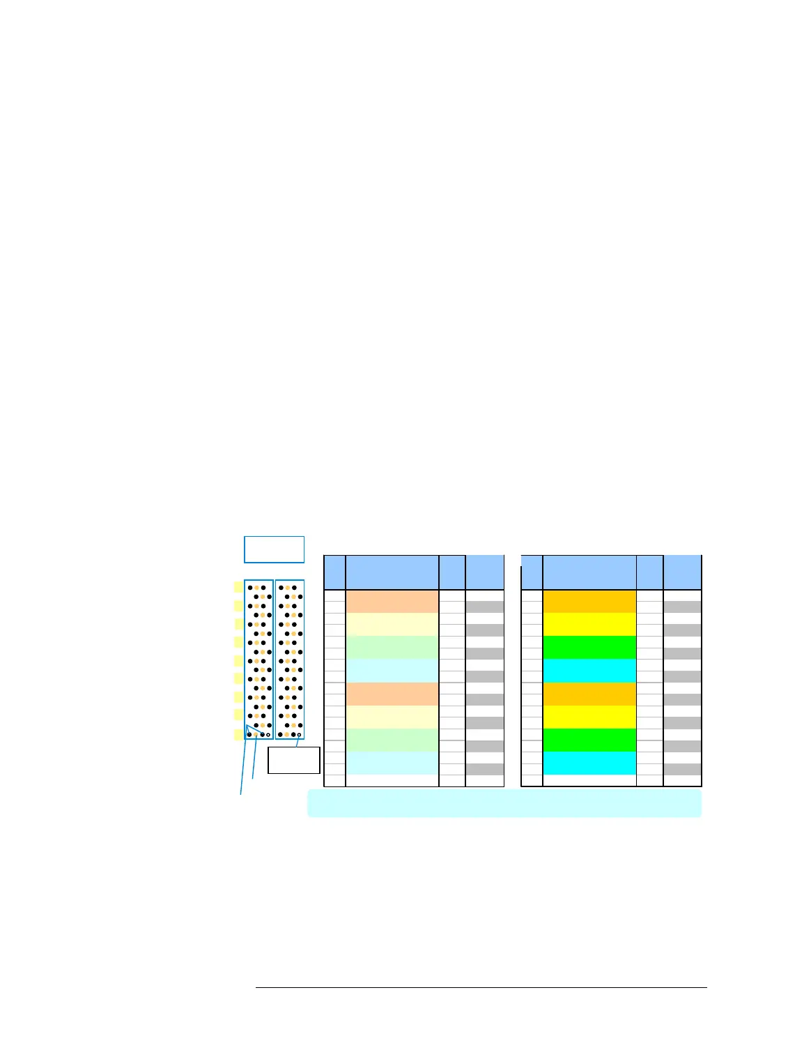
The MCA uses two pogo blocks: S2 (A) and S1 (D) pogo blocks.
Thus, the number of pogo pins in the MCA is twice as many as
other analog modules, where only the S2 (A) pogo blocks are used.
The following table shows the pad assignment for the Multi-site
Baseband Analog modules (MCA).
Table 1 Pogo Pin Assignments for Multi-site Baseband Analog Module
Pogo Signal GND Mode Pogo Signal GND Mode
Pad Pad Pad Value in Pad Pad Pad Value in
No. (Unit) PinConfig No. (Unit) PinConfig
01 DD- Unit 4 AGND 24 01 HH- Unit 8 AGND 32
02 DD+ (CLK) Unit 4 AGND 20 02 HH+ (CLK) Unit 8 AGND 28
03 CC- Unit 3AGND 23 03 GG- Unit 7AGND 31
04 CC+ (CLK) Unit 3 AGND 19 04 GG+ (CLK) Unit 7 AGND 27
05 BB- Unit 2 AGND 22 05 FF- Unit 6 AGND 30
06 BB+ (CLK) Unit 2 AGND 18 06 FF+ (CLK) Unit 6 AGND 26
07 AA- Unit 1 AGND 21 07 EE- Unit 5 AGND 29
08 AA+ (CLK) Unit 1 AGND 17 08 EE+ (CLK) Unit 5 AGND 25
09 D- Unit 4 AGND 8 09 H- Unit 8 AGND 16
10 D+ Unit 4 AGND 4 10 H+ Unit 8 AGND 12
11 C- Unit 3 AGND 7 11 G- Unit 7 AGND 15
12 C+ Unit 3 AGND 3 12 G+ Unit 7 AGND 11
13 B- Unit 2 AGND 6 13 F- Unit 6 AGND 14
14 B+ Unit 2 AGND 2 14 F+ Unit 6 AGND 10
15 A- Unit 1 AGND 5 15 E- Unit 5 AGND 13
16 A+ Unit 1 AGND 1 16 E+ Unit 5 AGND 9
17 CT1 --- FGND --- 17 CT2 (CLK) --- FGND ---
Orientation
Marker
Signal Pad
Unit 1 to 4: Source units for Source&Measure module, Measure units for Measure module
Unit 5 to 8: Measure units
S1
01
17
S2
S2 Pogo Block S1 Pogo Block
03
05
07
09
11
13
15
GND Pad
Pogo Blocks
per module

 Loading...


