Lesson 1 – Analog Clock Domain Description
371
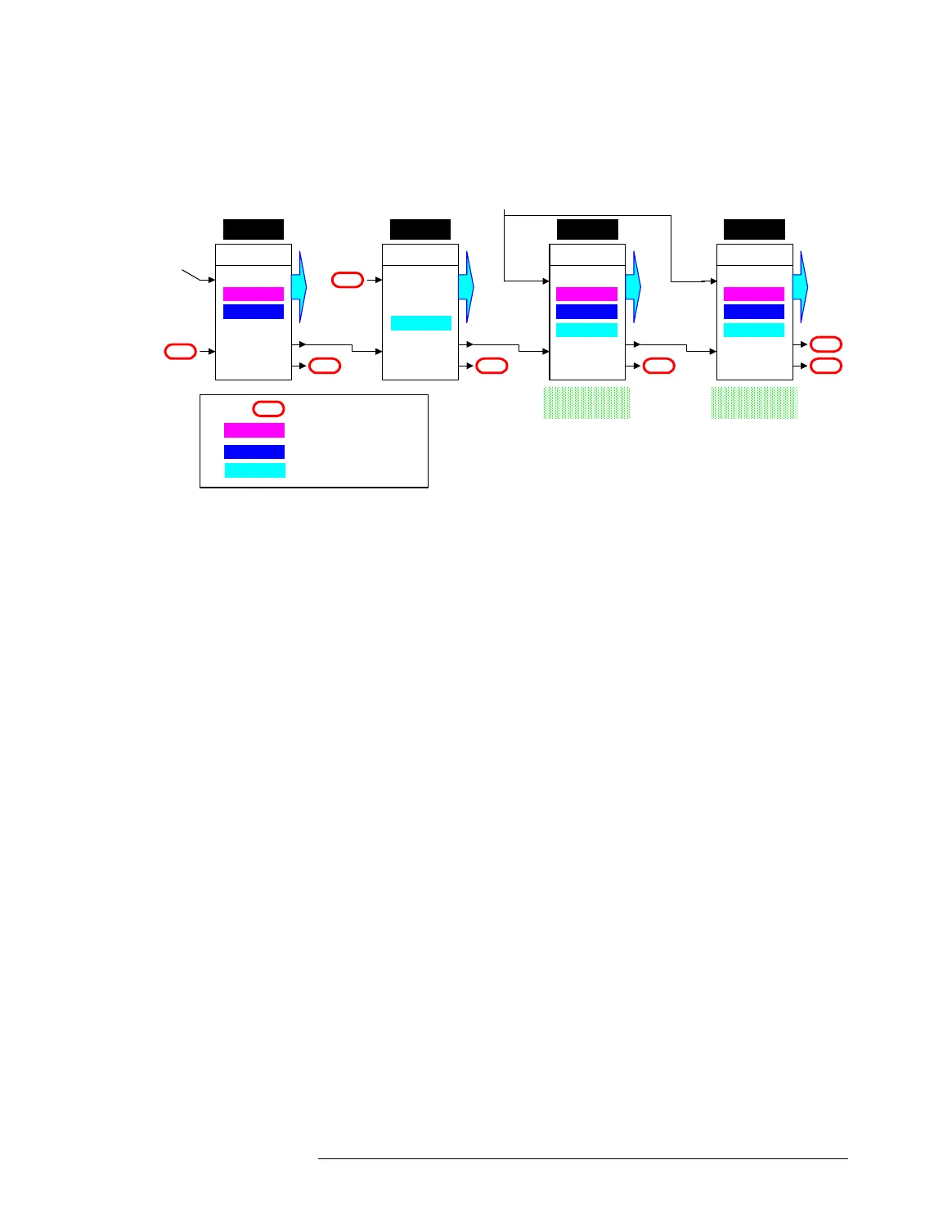
Clock Distribution 512 Testhead (with AMC, Digital Domain and Analog
Domain)
In the figure above, the clock board in card cage 1 can either
generated the clock signal with its own PLL and distribute it to
the slots in card cage 1, and to the next card cage (cage 3) via
Ring A, or it can distribute the input signal from the AMC. In both
cases, this is the clock signal for the whole digital clock domain.
The clock board in cage 3 can only forward the incoming clock
signal to the slots and via Ring A to the next card cage.
The clock boards of the card cages 4 and 2 can
• either receive the clock signal from an AMC (the same AMC feeds
both cages) and distribute it to the slots of their card cage. This
clock signal is for the analog clock domain, clock source is the
AMC,
• or generate a clock signal of the same frequency with their PLLs
and distribute it to the slots of their card cage. This clock signal is
also for the analog clock domain,
• and, at the same time, distribute the incoming clock signal at the
Ring input to the slots of their card cage. This clock signal is for the
digital clock domain. The clock boards of the card cage 4 can
forward only this clock signal (not the AMC or the PLL signal) via
Ring A.
Master
RING A
RING B
Ring
Ext.
C. Cage 1
NC
NC
SLOTS
Slave
RING A
RING B
Ring
Ext.
C. Cage 3
NC
NC
SLOTS
Slave
RING A
RING B
Ring
Ext.
C. Cage 4
NC
SLOTS
Slave
RING A
RING B
Ring
Ext.
C. Cage 2
NC
SLOTS
NC
AMC
(digital domain)
Analog Card Cage Analog Card Cage
Local PLL
Ring
External
Ring
Local PLL
External External
Ring
NC
Not Connected
Local PLL
External
Ring
Clock generated by PLL
Clock from AMC
Clock from the previous clock
board
Local PLL
AMC
(analog domain)

 Loading...


